


VR8105, VR8205, AND VR8305 DIRECT IGNITION COMBINATION GAS CONTROLS
69-1226—2 8
Check and Adjust Gas Input and Burner
Ignition
IMPORTANT
1. Do not exceed input rating stamped on
appliance nameplate, or manufacturer’s
recommended burner orifice pressure for size
orifice(s) used. Make certain primary air supply
to main burner is properly adjusted for complete
combustion. Follow appliance manufacturer
instructions.
2. IF CHECKING GAS INPUT BY CLOCKING
GAS METER: Make certain there is no gas flow
through the meter other than to the appliance
being checked. Other appliances must remain
off with the pilots extinguished (or deduct their
consumption from the meter reading). Convert
flow rate to Btuh as described in form 70-2602,
Gas Controls Handbook, and compare to Btuh
input rating on appliance nameplate.
3. IF CHECKING GAS INPUT WITH
MANOMETER: Make sure the gas control is in
the OFF position before removing outlet
pressure tap plug to connect manometer
(pressure gauge). Also move the gas control
knob back to the OFF position when removing
the gauge and replacing the plug. Before
removing inlet pressure tap plug, shut off gas
supply at the manual valve in the gas piping to
the appliance or, for LP, at the tank. Also shut off
gas supply before disconnecting manometer
and replacing plug. Repeat Gas Leak Test at
plug with main burner operating.
NOTE: Check the inlet pressure before adjusting the
pressure regulator.
Standard and Slow-Opening (H, K and M)
Models
1. Carefully check the main burner lightoff. Make sure
that the main burner lights smoothly and that all
ports remain lit.
2. Check the full rate manifold pressure listed on the
appliance nameplate. Gas control full rate outlet
pressure should match this rating.
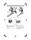
3. With main burner operating, check the control flow
rate using the meter clocking method or check
pressure using a manometer connected to the
outlet pressure tap on the control. See Fig. 6.
4. If necessary, adjust the pressure regulator to
match the appliance rating. See Tables 8 and 9
for factory-set nominal outlet pressure and
adjustment range.
a. Remove the pressure regulator adjustment cap
screw.
Using a screwdriver, turn the inner adjustment screw
(Fig. 6) clockwise to increase or
counterclockwise to decrease the gas pressure to
the burner.
b. Always replace the cap screw and tighten
firmly to prevent gas leakage.
5. If the desired outlet pressure or flow rate cannot be
achieved by adjusting the gas control, check the
gas control inlet pressure using a manometer at
the inlet pressure tap of the gas control. If the inlet
pressure is in the nominal range (see Tables 8
and 9), replace the gas control. Otherwise, take
the necessary steps to provide proper gas
pressure to the control.
NOTE: If the burner firing rate is above 150,000 Btuh
on VR8305 models (see Table 1 for VR8305
capacities), it may not be possible to deliver the
desired outlet pressure. This is an application
issue, not a control failure. Take whatever steps
are required to correct the situation.
Step-Opening (P) Models
Step-opening models require that you check and adjust
the full-rate pressure first and then check the step
pressure. The step pressure is not field adjustable.
1. Carefully check the main burner lightoff. Make sure
that the main burner lights smoothly and that all
ports remain lit.
2. Check the full rate manifold pressure listed on the
appliance nameplate. Gas control full rate outlet
pressure should match this rating.
3. With main burner operating, check the gas control
flow rate using the meter clocking method or check
pressure using a manometer connected to the
outlet pressure tap on the gas control. See Fig. 6.
4. If necessary, adjust the pressure regulator to
match the appliance rating. See Tables 8 and 9 for
factory-set nominal outlet pressure and adjustment
range.
a. Remove the pressure regulator adjustment cap
screw.
Using a screwdriver, turn the inner adjustment screw
(Fig. 6) clockwise to increase or
counterclockwise to decrease the gas pressure
to the burner.
b. Always replace the cap screw and tighten
firmly to prevent gas leakage.
5. If the desired outlet pressure or flow rate cannot be
achieved by adjusting the gas control, check the
gas control inlet pressure using a manometer at
the inlet pressure tap of the control. If the inlet
pressure is in the nominal range (see Tables 8 and
9), replace the control. Otherwise, take the
necessary steps to provide proper gas pressure to
the control.
6. Carefully check the burner lightoff at step pressure.
Make sure the burner lights smoothly and without
flashback to the orifice. Make sure all ports remain
lit. Cycle the burner several times, allowing at least
60 seconds between cycles for the regulator to
resume the step function. Repeat after allowing the
burner to cool. Readjust the full rate outlet
pressure, if necessary, to improve lightoff
characteristics.
Two-Stage (Q) Models
Two-stage models require that you check and adjust both
high and low pressure regulator settings. Two-stage
appliance operating sequences vary. Consult the
appliance manufacturer instructions for the specific
operating sequence and regulator adjustment procedure
for the appliance in which the control is installed.
1. Set appliance to operate on high.
2. Carefully check the main burner lightoff. Make sure
that the main burner lights smoothly and that all
ports remain lit.
3. Check the full rate (high) manifold pressure listed
on the appliance nameplate for high pressure. The
gas control full rate outlet pressure should match
this rating.
69-1226-2.fm Page 8 Thursday, November 13, 2003 12:50 PM