


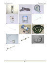
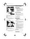
VR8105, VR8205, AND VR8305 DIRECT IGNITION COMBINATION GAS CONTROLS
3 69-1226—2
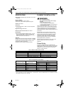
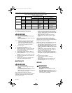
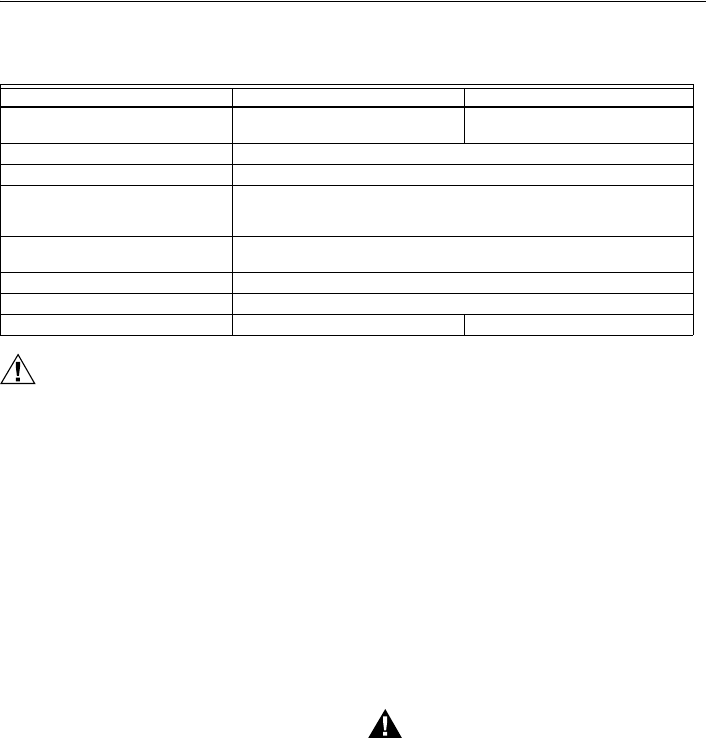
Table 6 shows additional specifications for the CE-only
models.
Table 6. VR8205A,H/VR8305A,H CE Models.
CAUTION
Equipment Damage Hazard.
Improper use can damage equipment.
Read the instructions before use. This control
must be installed in accordance with the rules in
force.
Water or Steam Cleaning
If a control gets wet, replace it. If the appliance is likely to
be cleaned with water or steam, protect (cover) the
control and wiring from water or steam flow. Mount the
control high enough above the bottom of the cabinet so it
does not get wet during normal cleaning procedures.
High Humidity or Dripping Water
Dripping water can cause the control to fail. Never install
an appliance where water can drip on the control. In
addition, high ambient humidity can cause the control to
corrode and fail. If the appliance is in a humid
atmosphere, make sure air circulation around the control
is adequate to prevent condensation. Also, regularly
check out the system.
Corrosive Chemicals
Corrosive chemicals can attack the control, eventually
causing a failure. If chemicals are used for routine
cleaning, avoid contact with the control. Where
chemicals are suspended in air, as in some industrial or
agricultural applications, protect the control with an
enclosure.
Dust or Grease Accumulation
Heavy accumulations of dust or grease can cause the
control to malfunction. Where dust or grease can be a
problem, provide covers for the control to limit
contamination.
Heat
Excessively high temperatures can damage the control.
Make sure the maximum ambient temperature at the
control does not exceed the rating of the control. If the
appliance operates at very high temperatures, use
insulation, shielding, and air circulation, as necessary, to
protect the control. Proper insulation or shielding should
be provided by the appliance manufacturer; verify proper
air circulation is maintained when the appliance is
installed.
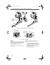
INSTALLATION
When Installing this Product…
1. Read these instructions carefully. Failure to follow
them could damage the product or cause a
hazardous condition.
2. Check the ratings given in the instructions and on
the product to make sure the product is suitable for
your application.
3. Installer must be a trained, experienced service
technician.
4. After installation is complete, check out product
operation as provided in these instructions.
WARNING
Fire or Explosion Hazard.
Can cause property damage, severe injury or
death.
Follow these warnings exactly:
1. Disconnect power supply before wiring to
prevent electrical shock or equipment damage.
2. To avoid dangerous accumulation of fuel gas,
turn off gas supply at the appliance service
valve before starting installation, and perform
Gas Leak Test after installation is complete.
3. Always install a sediment trap in gas supply
line to prevent contamination of gas control.
4. Do not force the gas control knob. Use only
your hand to turn the gas control knob. Never
use any tools. If the gas control knob does not
operate by hand, the gas control should be
replaced by a qualified service technician.
Force or attempted repair may result in fire or
explosion.
Specification VR8205A,H (CE Model Only) VR8305A,H (CE Model Only)
Main Valve Connection 1/2 in. ISO, 7/1 internal thread
(BSP.PL).
1/2 in., 3/4 in. ISO, 7/1 internal thread
(BSP.PL).
Ambient Temperature Range -20°C to +70°C (-4°F to +158°F)
Maximum Inlet Pressure 60 mbar (24 in. wc).
Pressure Regulation Servo regulator with adjustable outlet pressure; in accordance with EN 88
Class C.
Natural gas: 9 mbar, typical; LP: 20 mbar, typical.
Regulator Adjustment For natural gas, 7.5 mbar to 12.5 mbar field adjustable.
For LP gas, 20 mbar to 30 mbar field adjustable.
Ground Terminal 6.3 mm
Pressure Taps 9 mm OD
Valve Classification B+D C+D
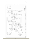
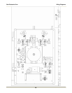
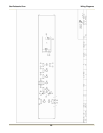
69-1226-2.fm Page 3 Thursday, November 13, 2003 12:50 PM