


VR8105, VR8205, AND VR8305 DIRECT IGNITION COMBINATION GAS CONTROLS
9 69-1226—2
4. With main burner operating, check the gas control
flow rate using the meter clocking method or check
pressure using a manometer connected to the
outlet pressure tap on the gas control. See Fig. 6.
5. If necessary, adjust the high pressure regulator to
match the appliance rating. See Tables 8 and 9 for
factory-set nominal outlet pressure and adjustment
range.
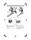
a. Remove the pressure regulator adjustment cap
(Fig. 6).
Using a screwdriver, turn the inner adjustment screw for
HI pressure clockwise to increase or
counterclockwise to decrease the gas pressure
to the burner.
6. After high pressure has been checked, check low
pressure regulation. Two-stage appliance
operating sequences vary. Consult the appliance
manufacturers instructions for the specific
operating sequence and regulator adjustment
procedure for the appliance in which the control is
installed and for instructions on how to prevent the
control from moving to high stage while checking
the low pressure regulator setting.
7. Check the low rate manifold pressure listed on the
appliance nameplate. Gas control low rate outlet
pressure should match this rating.
8. With main burner operating, check the gas control
flow rate as before (using the meter clocking
method or check pressure using a manometer
connected to the outlet pressure tap on the
control).
9. If necessary, adjust the low pressure regulator to
match the appliance rating. See Tables 8 and 9 for
factory-set nominal outlet pressure and adjustment
range.
a. Remove the pressure regulator adjustment cap
(Fig. 6).
Using a screwdriver, turn the inner adjustment screw for
LO pressure clockwise to increase or
counterclockwise to decrease the gas pressure
to the burner.
10. Once high and low pressure have been checked
and adjusted, replace pressure regulator
adjustment cap. If the desired outlet pressure or
flow rate cannot be achieved by adjusting the gas
control, check the control inlet pressure using a
manometer at the inlet pressure tap of the control.
If the inlet pressure is in the nominal range (see
Tables 8 and 9), replace the gas control.
Otherwise, take the necessary steps to provide
proper gas pressure to the control.
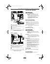
Check Safety Lockout (Slow-Opening
Controls Only)
1. With the system power off and the thermostat set
to call for heat, manually shut off the gas supply.
2. Energize ignition control and start timing safety
lockout time. When spark ignition terminates, stop
timing.
When using the VR8105H, VR8205H and
VR8305H step-opening control, the specified
ignition control safety lockout time must exceed 8.5
seconds for the system to function properly.
3. After spark cutoff, manually reopen the gas control
knob. No gas should flow to the main burner.
4. Reset the system by adjusting the thermostat
below room temperature, wait 30 seconds, and
then move the thermostat setting up to call for
heat. Normal ignition should occur.
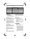
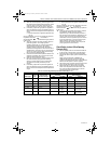
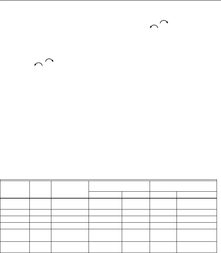
Table 8. Pressure Regulator Specification Pressures (in. wc).
a
Low Fire setting range for VR8305Q 1/2 in. by 1/2 in. and 1/2 in. by 3/4 in. is 1.5 to 3.0 in. wc.
Model Type
Type of
Gas
Nominal Inlet
Pressure Range
Factory Set Nominal Outlet
Pressure Setting Range
Step Full Rate Step Full Rate
Standard,
Slow
NAT 5.0-7.0 — 3.5 — 3.0-5.0
LP 12.0-14.0 — 10.0 — 8.0-12.0
Step NAT 5.0-7.0 0.9 3.5 None 0.7-1.7
LP 12.0-14.0 2.2 10.0 None 1.4-5.5
Two-stage NAT 5.0-7.0 — 1.7 Low
3.5 High
—
0.9-3.0 Low
a
3.0-5.0 High
LP 12.0-14.0 — 4.9 Low
10.0 High
— 3.5-5.5 Low
8.0-11.0 High
69-1226-2.fm Page 9 Thursday, November 13, 2003 12:50 PM