


6 • 909A & 919A OWNER/OPERATOR MANUAL
INSTALLATION
GENERAL
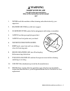
SAFE OPERATION REQUIRES PROPER
INSTALLATION AND PROPER WORK AREA.
1. Slicer should be installed in an area having adequate lighting.
2. Operator should have adequate space to move freely in the work area.
MACHINE MUST BE INSTALLED AND
OPERATED ON SOLID, LEVEL SUPPORT.
3. Installation should be made by an authorized Designated Berkel Service Location who will
demonstrate the slicer and register it for warranty.
NEVER TRY TO BYPASS SWITCHES
AND CIRCUITS PROVIDED.
DO NOT ACTIVATE BY WALL SWITCH.
4. After assembly, check to see that the following labels are in place on the slicer:
a. Warning label by power switch, part number 3175-00755.
b. Warning label on the front left corner of the housing, part number 3175-00650.
c. Warning label on the product table support arm, part number 3175-00767.
d. On the 919A, warning label on the sharpener cover, part number 3175-00768.
5. Post the Warning Wall Charts provided in a conspicuous place in the work area. They are part
numbers 3175-00557 and 3175-00541.
NEVER OPERATE ANY SLICER
WITHOUT THE LABELS IN PLACE.
INSTALLATION – MODEL 909A
1. Inspect to ensure all parts have been provided and the center plate knife guard is in place.
2. Place the slicer into position where it will be used.
INSTALLATION – MODEL 919A
1. Inspect to ensure all parts have been provided and the center plate knife guard is in place.
NSF regulations require the Model 919A slicer to be mounted on 4” legs or be equipped with the
optional Sure-Lock
®
lift. If your slicer is equipped with the optional Sure-Lock
®
lift, then proceed to
the “Assembly” section.