


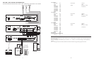
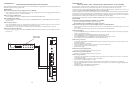
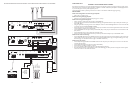

CONFIGURATION 13:
EMERGENCY VOICE ANNOUNCEMENT OVERRIDE
Voice Announcement Override is a non-programmable feature that lets the caller take priority over all paging functions and make a system-
wide emergency voice announcement page to all speakers. In addition to the PCM modules, this option requires a ProHold (digital announc-
er) and a normally open momentary switch supplied by the user.
The Override feature includes a quad beep pre-announce tone which can be enabled or inhibited through programming.
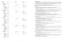
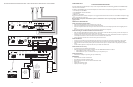
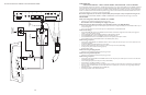
INSTALLATION:
STEP 1: Assembling Modules and Connecting the Amplifier
• Refer to step 1 on pages 5 and 17.
STEP 2: Connecting the Paging Amplifier
• Follow the same procedure described previously on page 5 or 17, step 5.
STEP 3: Connecting Optional Equipment
• Attach a 6-pin RJ11 modular jack to the wall next to the PCM2000 unit.
• Connect the audio output from the ProHold labeled Line 600 using the supplied RCA cable to the RJ11 modular jack terminals Y (yel-
low) and BK (black).
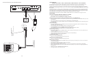
• Using the supplied stereo mini-plug, connect it to the TRIG input connector of the ProHold Digital Announcer. At the end of this cable,
you will see 3 bare wires labeled TIP, BARREL and RING.
• Connect the TIP wire to one of the terminals on the normally open connections of the customer-supplied switch and the other switch
terminal to the RJ11 modular jack terminal BL (blue).
• Connect the BARREL wire to the RJ11 modular jack terminal BL (blue). At this point you should have two wires connected to the BL
(blue) terminal.
• Connect the RING wire to the RJ11 modular jack terminal W (white).
• Connect a 6-pin RJ11 modular cable between the RJ11 modular jack and the Override RJ11 input on the PCMTIM module.
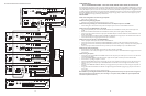
STEP 4: Switch and Control Settings
• Set the TEL-INT-SEL DIP switches on the PCMTIM module to match the paging output access from the telephone system based on the
type of telephone interface used. (See step 3 on page 5 if using Page Port Contact Closure; page 7 for Page Port VOX; page 9 for Loop
Start Trunk; page 11 for Ground Start Trunk; or page 13 for Station Level/Centrex.)
STEP 5: Testing Your System
• Connect the power supply PCMPS2 to the PCMCPU module to either the power jack 12V DC input or wire it to the 12V DC screw
terminals, observing polarity.
• Connect the Bogen amplifier to the AC power outlet (120V AC 60Hz).
• Set the volume on your Bogen amplifier to a half turn.
• Insert a pre-recorded normal bias audio tape into the ProHold cassette compartment.
• Once the ProHold announcer has downloaded the audio and the LOAD light goes "OFF", press the normally open customer supplied
switch once and listen for the all-call announcement.
12
29
PCM
TIM
POWER
TONE
VOLUME
BGM SRC
VOLUME
GND ST
IN
RT
BGM
SRC
NIGHT
RING
TEL
LINE
OVER
RIDE
NC
COM
NO
NC
COM
NO
RLY
ONE
RLY
TWO
S1
S2
S3
S4
S5
S6
S7
TEL
INT
SEL
0 1
POWER
- 1.5A
OUT
RT
GND
AUX
GND
S1
S2
S3
S4
0 1
SYS
ID
RUN
PROGRAM
DATA
LINK
12 VDC
1.5A
-
IN
RT
RT
IN
RT
IN
EM/SC
+ 12VDC
BOGEN
PA
LPBGM
PA
HPBGM
+
POWER
RD COM
+
-
RD A
RD B
ZONE A
ZONE B
ZONE C
OFF ON
TALKBACK
RT
IN
RD C
LOCAL
BGM
ZONE A
+
-
ZONE B
+
-
ZONE C
LPBGM
VOLUME
LO PWR
HI PWR
OUTPUT
BGM
OUT IN
PCM
ZPM
PCM
CPU
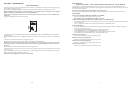
PBX
STATION
ACCESS
CENTREX
T
R
1 - Not used
2 - Not used
3 - Ring (Negative)
4 - Tip (Positive)
5 - Not used
6 - Not used
+
-
PCM PS2
RT
70V COM
BOGEN PAGING
AMPLIFIER
S1
S2
S3
S4
S5
S6
S7
TEL
INT
SEL
0 1
ZONE A
ZONE B
ZONE C
GLOBL BGM
ZONE C
ZONE B
ZONE A
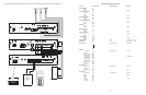
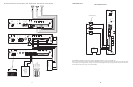
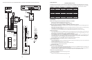
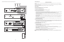
SETUP FOR CONFIGURATION 5:STATION LEVEL/CENTREX - 3-ZONE - ONE-WAY PAGING - SINGLE AMPLIFIER - 25/70V AC SPEAKERS