


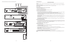
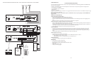
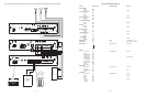

CONFIGURATION 5:
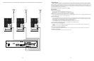
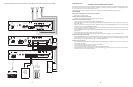
STATION LEVEL/CENTREX - 3-ZONE - ONE-WAY PAGING - SINGLE AMPLIFIER - 25/70V AC SPEAKERS
In this configuration, the PCM unit responds to a 90V AC 20Hz ringing signal in pins 3 & 4 of the TEL LINE jack on the PCMTIM module and
answers after the first full ring.As soon as it answers, the default timer is started.The default timer determines the maximum length of any
page.When a paging zone is selected, the VOX timer (if enabled) is started.This VOX timer repeatedly resets as long as audio is detected on
the line. If no audio is detected within the VOX time period, the page will end. If audio continues to be detected, the default timer will con-
trol the page length. Pins 1, 2, 5 & 6 are not used in this configuration.
Note: In this configuration, the unit will also respond to CPC pulses (interruption of loop current) disconnecting the line.
The required setup includes PCMTIM -PCMCPU - PCMZPM - PCMPS2. Modules must be assembled, from left to right, in this order.
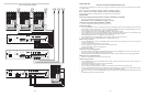
INSTALLATION:
STEP 1: Assembling Modules PCMTIM to PCMCPU and to PCMZPM
• Follow the same procedure described previously on page 5,step 1.
Note: Do NOT connect the PCMPS2 (power supply) at this point.
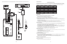
STEP 2: Connecting the Station Level/Centrex from the Telephone System to the PCMTIM Module
• Take the Station Level/Centrex pair from the telephone system and wire it to the RJ11 TEL-LINE jack in the PCMTIM module to pins 3
and 4 (red and green).
• Use a 4 or 6-pin modular cord to connect the RJ11 to the TEL-LINE input on the PCMTIM module.
STEP 3: Switch Settings
• Set the TEL-INT-SEL DIP switches on the PCMTIM module for Station Level/Centrex configuration: switch 6 ON (to the right) and
switches 1, 2, 3, 4, 5 & 7 OFF (to the left).
• Set the SYS-ID DIP switches on the PCMCPU module to the OFF position (to the left).
• Set the RUN-PROGRAM switch on the PCMCPU module to the RUN mode (up).
• Set the Talk Back DIP switches on the PCMZPM module to the OFF position (to the left) for all zones.
• Set the OUTPUT switch on the PCMZPM module to the HI-PWR position (down).
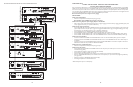
STEP 4: Testing your System
• Connect power supply PCMPS2 to the PCMCPU module to either the power jack 12V DC input or wire it to the 12V DC screw ter-
minals observing polarity.
• At this point all the power LEDs should be lit on each module.
• Access the Station Level/Centrex line from the phone system and verify access tones (double beep).
• At this point, the system should be functioning properly.
• Disconnect Power Supply.
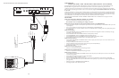
STEP 5: Connecting the Paging Amplifier
• Follow the same procedure described previously on page 5,step 5.
STEP 6: Connecting 25/70V AC Speakers
• Follow the same procedure described previously on page 5,step 6.
STEP 7: Testing your System
• Connect the power supply PCMPS2 to the PCMCPU module to either the power jack 12V DC input or wire it to the 12V DC screw
terminals observing polarity.
• Connect the Bogen amplifier to the AC power outlet (120V AC 60Hz).
• Set the volume on your Bogen amplifier to a 1/2 turn.
• Access the Station Level/Centrex port from the telephone system and listen (on the handset) for the confirmation tone (double beep).
• Dial 01 to access zone ONE and listen (on the handset and also to the speakers) for a pre-announce tone (single beep) followed by
your page (audio).
• Follow the same steps for ZONES TWO (02) and THREE (03).
• Set the Bogen amplifier to the desired volume level.
28
13
PCM
TIM
POWER
TONE VOLUME
BGM SRC
VOLUME
GND ST
IN
RT
BGM
SRC
NIGHT RING
TEL
LINE
OVER RIDE
NC
COM
NO
NC
COM
NO
RLY ONE
RLY TWO
S1
S2
S3
S4
S5
S6
S7
TEL
INT
SEL
0 1
G
BK
R
Y
BL
W
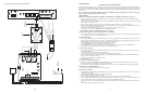
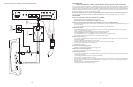
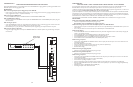
Contact closure
Dry audio input to PCMTIM (from ProHold)
Not used
Not used
Dry audio input to PCMTIM (from ProHold)
Contact closure
6 CONDUCTOR
MODULAR
CABLE
RJ 11
MODULAR BOX
PROHOLD
TIP
BARREL
RING
NORMALLY OPEN
CUSTOMER
SUPPLIED SWITCH
POWER
ON/OFF
12V
AC/DC
LINE
600
SPKR.
ON/OFF
1 WATT
VOLUME
TRIG
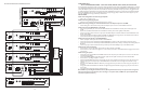
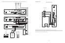
SETUP FOR CONFIGURATION 13: EMERGENCY VOICE ANNOUNCEMENT OVERRIDE