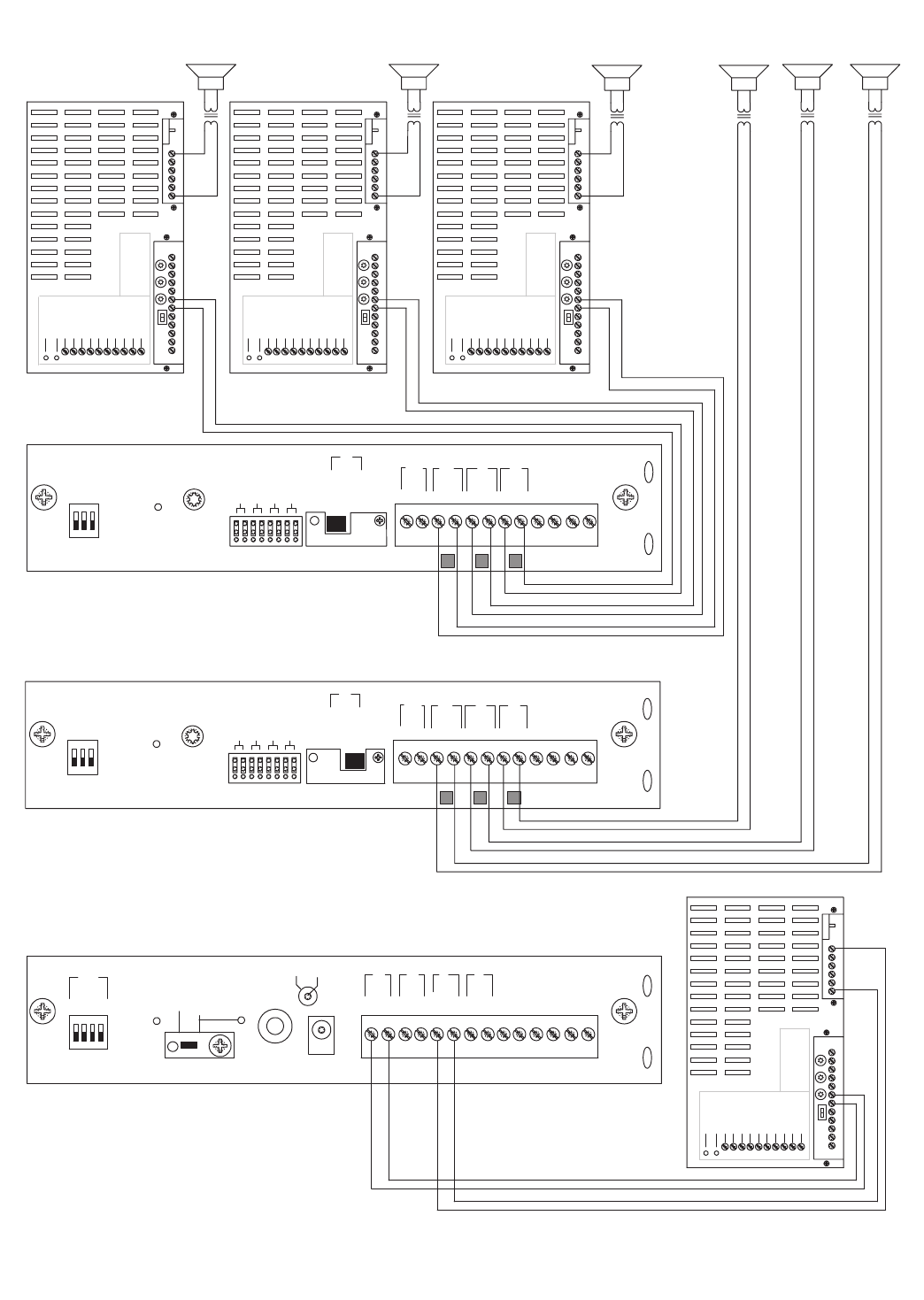
CONFIGURATION 8:
TWO-WAY TALK BACK EXTENDED PAGING SYSTEM
This configuration is essentially the same as the two-way paging system described previously on page 17.The main difference is the addition
of a satellite assembly.
The required setup includes: PCMTIM - 2 PCMCPU - PCMTBM - 4 PCMZPM - 2 PCMPS2
Note: Talk Back is only available in High-Power Zones with 25/70V AC speakers.
The paging access output from the telephone system must support two-way communications.
INSTALLATION:
STEP 1: Assembling Master Modules PCMTIM to PCMCPU to PCMTBM and to PCMZPM
• Follow the same procedure described previously on page 17, step 1.
Note: Do NOT connect the PCMPS2 (power supply) at this point.
STEP 2: Assembling Satellite Modules PCMCPU to PCMZPM
• Follow the same procedure described previously on page 15, step 2.
STEP 3: Switch Settings
• Set the TEL-INT-SEL DIP switches on the PCMTIM module to match the paging output access from the telephone system based on the
type of telephone interface used. (See step 3 on page 5 if using Page Port Contact Closure; page 7 for Page Port VOX; page 9 for Loop
Start Trunk; page 11 for Ground Start Trunk; or page 13 for Station Level/Centrex.)
• Set the SYS-ID DIP switches on the master PCMCPU module to the OFF position (to the left).
• Set the SYS-ID DIP switches on the first satellite PCMCPU module to the following configuration: switch 1 to the ON position (to the
right), switches 2, 3, & 4 to the OFF position (to the left). See additional SYS-ID settings on page 38.
• Set the RUN-PROGRAM switch on each PCMCPU to the RUN mode (up).
• Set the TALK BACK switches on the PCMZPM modules to the ON position (to the right) for all zones.
• Set the OUTPUT switch on each PCMZPM module to the HI-PWR position (down).
STEP 4: Testing your System
• Connect one PCMPS2 power supply to each PCMCPU module to either the power jack 12V DC input or wire it to the 12V DC screw
terminals, observing polarity.
• At this point all the power LEDs should be lit on each module.
• Access the paging from the phone system and verify access tones (double beep).
• At this point, the system should be functioning properly.
• Disconnect Power Supply.
STEP 5: Connecting the Paging Amplifier
• Locate the terminals on the PCMTBM module labeled PA OUT/RT and wire to the COMMON and either 25 or 70V output on the
Bogen paging amplifier (either TPU-Series, GS-Series or Classic Series).
• Locate the terminals on the PCMTBM module labeled PA IN/RT and wire to the TIP and RING input on the Bogen paging amplifier.
STEP 6: Connecting 25/70V AC Speakers
• Follow the same procedure described previously on page 5,step 6.
STEP 7: Testing your System
• Connect a PCMPS2 power supply to each PCMCPU module to either the power jack 12V DC input or wire it to the 12V DC screw
terminals observing polarity.
• Connect the Bogen amplifier to the AC power outlet (120V AC 60Hz).
• Set the volume on your Bogen amplifier to a 1/2 turn.
• Access the paging from the telephone system and listen (on the handset) for the confirmation tone (double beep).
• Dial 01 to access ZONE ONE and listen (on the handset and also to the speakers) for a pre-announce tone (single beep).At this point,
you should be able to hear audio from the location where the speaker for ZONE ONE is installed.
• The volume and delay controls on the PCMTBM module, control the audio back into the handset.Adjust these controls for best opera-
tion.
• Set the Bogen amplifier to the desired volume level.
22
19
PCM
ZPM
POWER
RD COM
+
-
RD A
RD B
ZONE A
ZONE B
ZONE C
OFF ON
TALKBACK
RT
IN
RD C
LOCAL
BGM
ZONE A
+
-
ZONE B
+
-
ZONE C
LPBGM
VOLUME
LO PWR
HI PWR
OUTPUT
BGM
OUT IN
POWER LED
PEAK LEVEL
APHEX
TREBLE
BASS
VOX SENS
RING VOLUME
MUSIC MUTE
MUSIC
VOLUME
MIC VOLUME
TEL VOLUME
ALC
MODEL TPU-100B
100WATT AMPLIFIER
BOGEN
POWER LED
PEAK LEVEL
APHEX
TREBLE
BASS
VOX SENS
RING VOLUME
MUSIC MUTE
MUSIC
VOLUME
MIC VOLUME
TEL VOLUME
ALC
MODEL TPU-100B
100WATT AMPLIFIER
BOGEN
POWER LED
PEAK
LEVEL
APHEX
TREBLE
BASS
VOX SENS
RING VOLUME
MUSIC MUTE
MUSIC
VOLUME
MIC VOLUME
TEL VOLUME
ALC
MODEL TPU-100B
100WATT AMPLIFIER
BOGEN
PCM
ZPM
POWER
RD COM
+
-
RD A
RD B
ZONE A
ZONE B
ZONE C
OFF ON
TALKBACK
RT
IN
RD C
LOCAL
BGM
ZONE A
+
-
ZONE B
+
-
ZONE C
LPBGM
VOLUME
LO PWR
HI PWR
OUTPUT
BGM
OUT IN
POWER
- 1.5 A
OUT
RT
GND
AUX
GND
S1
S2
S3
S4
0 1
SYS
ID
RUN
PROGRAM
DATA
LINK
12 VDC
1.5 A
-
IN
RT
RT
IN
RT
IN
EM/SC
+ 12VDC
BOGEN
PA
LPBGM
PA
HPBGM
+
PCM
CPU
POWER LED
PEAK LEVEL
APHEX
TREBLE
BASS
VOX SENS
RING VOLUME
MUSIC MUTE
MUSIC
VOLUME
MIC VOLUME
TEL VOLUME
ALC
MODEL TPU-100B
100WATT AMPLIFIER
BOGEN
ZONE A
ZONE B
ZONE C
GLOBL BGM
ZONE A
ZONE B
ZONE C
GLOBL BGM
ZONE C
ZONE B
ZONE A
ZONE A
ZONE B
ZONE C
SETUP FOR CONFIGURATION 10: 6 ZONES - ONE-WAY PAGING - MIXED HIGH- AND LOW-POWER ZONES -
25/70V AC OR SELF-AMPLIFIED SPEAKERS


