


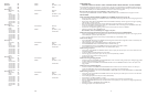

Zone #’s S1 S2 S3 S4
Master 1-9 0000
Satellite
1 10-18 1 000
2 19-27 0 1 00
3 28-36 1100
4 37-45 0 0 1 0
5 46-54 1 0 1 0
6 55-63 0 110
7 64-72 1110
8 73-81 0001
9 82-90 1 001
10 91-99 0 1 0 1
Contents
SECTION I - APPLICATON CONFIGURATIONS....................................................................................................................................................4-33
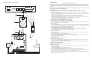
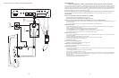
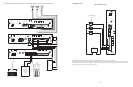
Configuration 1. Page Port Contact Closure - 3-Zone - One-Way Paging - Single Amplifier - 25/70V AC Speakers
Setup Drawing................................................................................................................................................................................................................................4
Description ......................................................................................................................................................................................................................................5
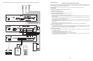
Configuration 2. Page Port VOX Circuit - 3-Zone - One-Way Paging - Single Amplifier - 25/70V AC Speakers
Setup Drawing................................................................................................................................................................................................................................6
Description ......................................................................................................................................................................................................................................7
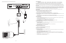
Configuration 3. Loop Start Trunk - 3-Zone - One-Way Paging - Single Amplifier - 25/70V AC Speakers
Setup Drawing................................................................................................................................................................................................................................8
Description ......................................................................................................................................................................................................................................9
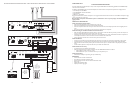
Configuration 4. Ground Start Trunk - 3-Zone - One-Way Paging - Single Amplifier - 25/70V AC Speakers
Setup Drawing................................................................................................................................................................................................................................10
Description ......................................................................................................................................................................................................................................11
Configuration 5. Station Level/Centrex - 3-Zone - One-Way Paging - Single Amplifier - 25/70V AC Speakers
Setup Drawing................................................................................................................................................................................................................................12
Description ......................................................................................................................................................................................................................................13
Configuration 6. Extended Paging System
Setup Drawing................................................................................................................................................................................................................................14
Description ......................................................................................................................................................................................................................................15
Configuration 7.Two-Way Talk Back Paging System
Setup Drawing................................................................................................................................................................................................................................16
Description ......................................................................................................................................................................................................................................17
Configuration 8.Two-Way Talk Back Extended Paging System
Setup Drawing................................................................................................................................................................................................................................18
Description ......................................................................................................................................................................................................................................19
Configuration 9. 3-Zone - One-Way Paging - Low-Power System - Dedicated Amplifiers or Self-Amplified Speakers
Setup Drawing................................................................................................................................................................................................................................20
Description ......................................................................................................................................................................................................................................21
Configuration 10. 6 Zones - One-Way Paging - Mixed High- and Low-Power Zones - 25/70V AC or Self-Amplified Speakers
Setup Drawing................................................................................................................................................................................................................................22
Description ......................................................................................................................................................................................................................................23
Configuration 11. Microphone Override
Setup Drawing................................................................................................................................................................................................................................24
Description ......................................................................................................................................................................................................................................25
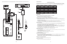
Configuration 12. DFT120 & TAMB Wiring Diagram - Loop Start Trunk, Ground Start Trunk, or Station Level
Setup Drawing................................................................................................................................................................................................................................26
Description ......................................................................................................................................................................................................................................27
Configuration 13. Emergency Voice Announcement Override
Setup Drawing................................................................................................................................................................................................................................28
Description ......................................................................................................................................................................................................................................29
Configuration 14. DTMF Microphone Zone Paging
Setup Drawing................................................................................................................................................................................................................................30
Description ......................................................................................................................................................................................................................................31
Configuration 15. Single Amplifier Background Music Line-Level Signal
Setup Drawing................................................................................................................................................................................................................................32
Description ......................................................................................................................................................................................................................................32
Configuration 16. Relay Driver Output
Setup Drawing................................................................................................................................................................................................................................33
Description ......................................................................................................................................................................................................................................33
SECTION II - Programming......................................................................................................................................................................................................34-38
System Programming ................................................................................................................................................................................................34
Feature Codes and Defaults Chart........................................................................................................................................................................35-37
SYS-ID Switch Settings Chart for Additional Satellite Systems ......................................................................................................................38
APPENDIX
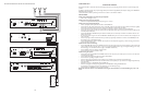
Module Assembly Illustrations ................................................................................................................................................................................38
38
3
SYS-ID SWITCH SETTINGS CHART FOR ADDITIONAL SATELLITE SYSTEMS
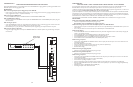
54-5019-02R2
Printed in U.S.A. 0107
S/N
MADE IN KOREA
......................
.......................
......................
....................
....................
..................
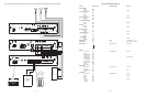
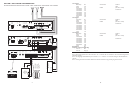
PCM
TIM
PCM
CPU
PCM
TBM
PCM
ZPM
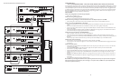
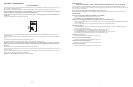
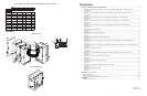
APPENDIX
Module Assembly
Completed Assembly
LOCKING
TAB
LOCKING
TAB
LOCKING
SLOT
LOCKING
TAB
LOCKING
SLOT
ALIGN
CONNECTORS
SO LOCKING
RIDGE FACES
HEADER WALL
ALIGN
POLARIZING
TAB IN SLOT
SCREW
CLAMP
TAB &
SLOT
Align polarizing tab in slot
Align connectors
so locking ridge
faces header wall.
Ribbon Cable Connector
6-pin Connector