


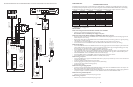


CONFIGURATION 6:
EXTENDED PAGING SYSTEM
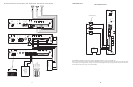
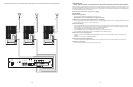
This illustration shows the wiring between a master assembly and a satellite assembly in a PCM system with a satellite assembly for one-way paging.
As described previously, the required setup for one-way basic configuration includes: PCMTIM, PCMCPU, PCMZPM, and the power supply
PCMPS2. For PCM systems with satellites (more than 9 zones), the number of modules and power supplies will increase as follows:
# ZONES # PCMTIM # PCMCPU # PCMZPM* # PCMPS2
1 to 9 111to 3 1
10 to 18 1 2 4 to 6 2
19 to 27 1 3 7 to 9 3
28 to 36 1 4 10 to 124
37 to 45 1 5 13 to 155
46 to 54 1 6 16 to 186
55 to 63 1 7 19 to 21 7
64 to 72 1 8 22 to 24 8
73 to 811 9 25 to 27 9
82 to 90 110 28 to 30 10
91 to 99 11131 to 33 11
Notice that for every 9 zones, one additional PCMCPU and one additional PCMPS2 are needed.
* 1 PCMZPM for every 1-3 paging zones.
INSTALLATION:
STEP 1: Assembling Master Modules PCMTIM to PCMCPU and to PCMZPM
• Follow the same procedure described previously on page 5,step 1.
Note: Do NOT connect the PCMPS2 (power supply) at this point.
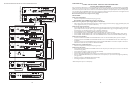
STEP 2: Assembling Satellite Modules PCMCPU to PCMZPM (see Illustration on page 38)
• Plug the 6-pin power connector from the PCMZPM module to the PCMCPU module jack (J2.) Be sure that the locking ridge faces the
header wall. (Green wire to the top).
• Plug the 26-pin ribbon cable from the PCMZPM module to the PCMCPU module 26-pin connector (J1). Be sure to align the polarizing
tab in slot. (Pin 1 red stripe to the top).
• The satellite systems are usually installed below the the master assembly and must be within 3 feet of each other.
• Use an RCA cable to connect the PCMCPU modules from DATA LINK to DATA LINK RCA connectors. (See drawing.)
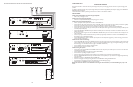
STEP 3: Switch Settings
• Set the TEL-INT-SEL DIP switches on the PCMTIM module to match the paging output access from the telephone system based on the
type of telephone interface used. (See step 3 on page 5 if using Page Port Contact Closure; page 7 for Page Port VOX; page 9 for Loop
Start Trunk; page 11 for Ground Start Trunk; or page 13 for Station Level/Centrex.)
• Set the SYS-ID DIP switches on the master PCMCPU module to the OFF position (to the left).
• Set the SYS-ID DIP switches on the first satellite PCMCPU module to the following configuration: Switch 1 to the ON position (to the
right). Switches 2, 3, & 4 to the OFF position (to the left). See SYS-ID switch settings chart on page 38 for additional satellite systems.
• Set the RUN-PROGRAM switch on the PCMCPU module to the RUN mode (up).
• Set the TALK BACK switches on the PCMZPM modules to the OFF position (to the left) for all zones.
• Set the OUTPUT switch on all the PCMZPM modules to the HI-PWR position (down).
STEP 4: Testing your System
• Connect one PCMPS2 power supply to each PCMCPU module either by the power jack 12V DC input or wire it to the 12V DC screw
terminals, observing polarity.
• At this point all the power LEDs should be lit on each module.
• Access the paging from the phone system and verify access tones (double beep).
• At this point, the system should be functioning properly.
• Disconnect Power Supply.
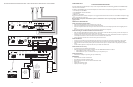
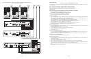
STEP 5: Connecting the Paging Amplifier
• Locate the terminals on both PCMCPU modules labeled PA OUT/RT and wire them to the COMMON and 25V or 70V output on the
Bogen paging amplifier (either TPU-Series, GS-Series or Classic Series).
• Locate the terminals on the PCMCPU modules labeled PA IN/RT and wire to the TIP and RING input on the Bogen paging amplifier.At
this point, the amplifier is connected in parallel to the master PCMCPU module and the satellite PCMCPU module.
STEP 6: Connecting 25/70V AC Speakers
• Follow the same procedure described previously on page 5,step 6.
STEP 7: Testing your System
• Follow the same procedure described previously on page 5,step 7.
26
15
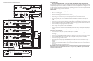
PCM
TIM
POWER
TONE
VOLUME
BGM SRC
VOLUME
GND ST
IN
RT
BGM
SRC
NIGHT
RING
TEL
LINE
OVER
RIDE
NC
COM
NO
NC
COM
NO
RLY
ONE
RLY
TWO
S1
S2
S3
S4
S5
S6
S7
TEL
INT
SEL
0 1
G
BK
R
Y
BL
W
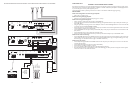
Not used
Play status contact common
Audio output (-)
Audio output (+)
Play status contact
Not used
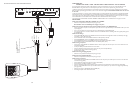
6 CONDUCTOR
MODULAR
CABLE
RJ 11
MODULAR
BOX
8 600DL LS
VOLUME
1 6 1 6
1 2 3 4 5 6 7 8 9 101112
1 2 3 4 5 6 7 8 9 10 11 12
IN USE PLAY RECORD
POWER
12VDC 1A
COMPLIES WITH PART 68, FCC RULES
FCC REGISTRATION NUMBER:
CD23CH-17705-KX-N
RINGER EQUIVALENCE: 1.2 B
TAM B
TELEPHONE ACCESS
MODULE
BOGEN
COMMUNICATIONS
RAMSEY, NJ
MODE
24 VDC PWR SUPPLY
48 VDC PWR SUPPLY
CONFIRMATION TONE
PREANNOUNCE TONE
VOX DISABLE
VOX ENABLE
OFF
-----
S1, S2
S3
S4
S5
-----
ON
S1, S2
-----
S4
S3
-----
S5
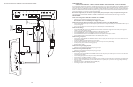
PHONE SYSTEM
T
R
+M
-M
EXT VOX ENABLE
PT
PR
PAGING OUTPUT
N.O.
COM
CONTACT CLOSURE A
+24/48
-24/48
POWER SUPPLIES
MODE
SWITCHES
BGM
VOL.
BGM
IN
TONE VOLUME
MIN MAX
VOX DELAY
MIN MAX
PAGING TIME
MIN MAX
OFF ON
G
BK
R
Y
BLW
DFT120
PBX
ANALOG LINE
Note Switch settings:
Off - Up, On - Down
24/48V DC
POWER
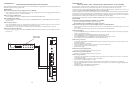
SUPPLY
SETUP FOR CONFIGURATION 12:DFT120 & TAMB WIRING DIAGRAM - LOOP START TRUNK,GROUND START TRUNK OR STATION LEVEL