


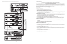


CONFIGURATION 9:
3-ZONE - ONE-WAY PAGING - LOW-POWER SYSTEM - DEDICATED AMPLIFIERS OR SELF-AMPLIFIED SPEAKERS
Low-Power System is a switch-selectable feature that allows the system designer to use dedicated amplifiers or self-amplified speakers on the
zone outputs.The PCMZPM module that is to be used as a low-power module will switch only low-level signals to the zone outputs for use
with dedicated amplifiers or self-amplified speakers. Note that its output switch is set to LO PWR. In this example, three TPU100B amplifiers
are used but amplified speakers can be substituted.
Note: Low-Power Systems do not support two-way paging.
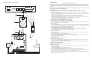
INSTALLATION:
STEP 1: Assembling Modules
• Follow the same procedure described previously on page 5,step 1.
Note: Do NOT connect the PCMPS2 (power supply) at this point.
STEP 2: Connecting Telephone System Paging Output to the PCMTIM
• Refer to paging access modes described previously in Step 2 on pages 5 (paging port/contact closure), 7 (paging port/VOX), 9 (loop start
trunk), 11 (ground start trunk), or 13 (station level/Centrex).
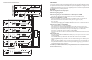
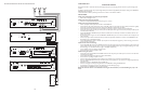
STEP 3: Switch Settings
• Set the TEL-INT-SEL DIP switches on the PCMTIM module to match the paging output access from the telephone system based on the
type of telephone interface used. (See step 3 on page 5 if using Page Port Contact Closure; page 7 for Page Port VOX; page 9 for Loop
Start Trunk; page 11 for Ground Start Trunk; or page 13 for Station Level/Centrex.)
• Set the SYS-ID switches on the PCMCPU to the OFF position (to the left).
• Set the TALKBACK switches on the PCMZPM to the OFF position (to the left) for all zones.
• Set the LO PWR / HI PWR OUTPUT switch on the PCMZPM to the LO PWR position (up).
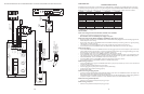
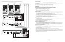
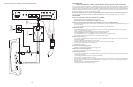
STEP 4: Connecting the Paging Amplifiers
• Locate the terminals on the PCMZPM module labeled ZONE A and connect to the TIP and RING terminals of the amplifier(s) for
ZONE A.
• Follow the same procedure for ZONE B and ZONE C.
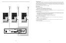
STEP 5: Connecting Self-Amplified Speakers
• Locate the terminals on the amplifiers labeled COM and 25V or 70V AC and connect the speakers related to that particular zone.
STEP 6: Testing Your System
• Follow the same procedure described previously on page 5,step 7.
20
21
PCM
ZPM
POWER
RD COM
+
-
RD A
RD B
ZONE A
ZONE B
ZONE C
OFF ON
TALKBACK
RT
IN
RD C
LOCAL
BGM
ZONE A
+
-
ZONE B
+
-
ZONE C
LPBGM
VOLUME
LO PWR
HI PWR
OUTPUT
BGM
OUT IN
POWER LED
PEAK LEVEL
APHEX
TREBLE
BASS
VOX SENS
RING VOLUME
MUSIC MUTE
MUSIC VOLUME
MIC VOLUME
TEL VOLUME
ALC
MODEL TPU-100B
100WATT AMPLIFIER
BOGEN
POWER LED
PEAK LEVEL
APHEX
TREBLE
BASS
VOX SENS
RING VOLUME
MUSIC MUTE
MUSIC VOLUME
MIC VOLUME
TEL VOLUME
ALC
MODEL TPU-100B
100WATT AMPLIFIER
BOGEN
POWER LED
PEAK LEVEL
APHEX
TREBLE
BASS
VOX SENS
RING VOLUME
MUSIC MUTE
MUSIC VOLUME
MIC VOLUME
TEL VOLUME
ALC
MODEL TPU-100B
100WATT AMPLIFIER
BOGEN
ZONE A
ZONE B
ZONE C
GLOBL BGM
ZONE C
ZONE B
ZONE A
SETUP FOR CONFIGURATION 9:3-ZONE - ONE-WAY PAGING - LOW-POWER SYSTEM - DEDICATED AMPLIFIERS OR SELF-AMPLIFIED SPEAKERS