


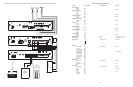


Clock Set 060 HHMM 00:00
Clock Sync. 067 HHMM (See Note 3 - p. 37)
Inhibit 068 Inhibit
Enable 069
Time Trigger 1
Zone Group *81 Zone Numbers No Zones
Inhibit 110 Inhibit
Enable 111 HHMM (See Note 3 - p. 37)
2-Second Tone 112
3-Second Tone 113 3-Second Tone
4-Second Tone 114
5-Second Tone 115
6-Second Tone 116
7-Second Tone 117
8-Second Tone 118
Chime 119
Time Trigger 2
Zone Group *82 Zone Numbers No Zones
Inhibit 120 Inhibit
Enable 121 HHMM (See Note 3 - p. 37)
2-Second Tone 122
3-Second Tone 123 3-Second Tone
4-Second Tone 124
5-Second Tone 125
6-Second Tone 126
7-Second Tone 127
8-Second Tone 128
Chime 129
Time Trigger 3
Zone Group *83 Zone Numbers No Zones
Inhibit 130 Inhibit
Enable 131 HHMM (See Note 3 - p. 37)
2-Second Tone 132
3-Second Tone 133 3-Second Tone
4-Second Tone 134
5-Second Tone 135
6-Second Tone 136
7-Second Tone 137
8-Second Tone 138
Chime 139
Time Trigger 4
Zone Group *84 Zone Numbers No Zones
Inhibit 140 Inhibit
Enable 141 HHMM (See Note 3 - p. 37)
2-Second Tone 142
3-Second Tone 143 3-Second Tone
4-Second Tone 144
5-Second Tone 145
6-Second Tone 146
7-Second Tone 147
8-Second Tone 148
Time Trigger 5
Zone Group *85 Zone Numbers No Zones
Inhibit 150 Inhibit
Enable 151 HHMM (See Note 3 - p. 37)
2-Second Tone 152
3-Second Tone 153 3-Second Tone
4-Second Tone 154
5-Second Tone 155
6-Second Tone 156
7-Second Tone 157
8-Second Tone 158
Chime 159
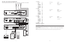
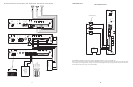
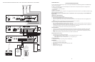
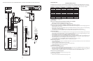
CONFIGURATION 1:
PAGE PORT CONTACT CLOSURE - 3-ZONE - ONE-WAY PAGING - SINGLE AMPLIFIER - 25/70V AC SPEAKERS
In this configuration, the PCM unit responds to a contact closure on pins 2 & 5 of the TEL LINE jack on the PCMTIM module shorting the
+5V source to its ground.When the closure is removed, the page ends.Audio is provided to the system through a separate pair of leads on
pins 3 & 4 of the TEL LINE jack on the PCMTIM module. Pins 1 & 6 are not used in this configuration.
Note:The audio pair (page port) must pass DTMF in order to select a zone.
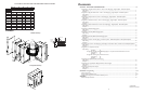
The required setup includes PCMTIM - PCMCPU - PCMZPM - PCMPS2. Modules must be assembled, from left to right, in this order.
INSTALLATION:
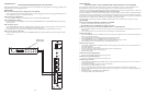
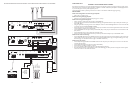
STEP 1:Assembling Modules PCMTIM to PCMCPU and to PCMZPM (see Illustration on page 38)
• Plug the 6-pin power connector from the PCMCPU module to the PCMTIM module jack (J2). Be sure that the locking ridge faces head-
er wall. (Green wire to the top.)
• Plug the 26-pin ribbon cable from the PCMCPU module to the PCMTIM module 26-pin connector (J1). Be sure to align the polarizing
tab in slot. (Pin 1 red stripe to the top.)
• Place the modules together and dress the connector cables away from the sheet metal so they will not get pinched.
• Push the two units together while aligning the locking tabs in the PCMTIM module to the locking slots in the PCMCPU module. Slide
the two units until the faces of both units are even.
• Secure the two units together by tightening a screw into the screw clamp tab in the back of the PCMTIM.
• Follow the same steps to add the PCMZPM module.
Note: Do NOT connect the PCMPS2 (power supply) at this point.
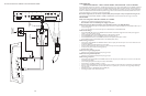
STEP 2: Connecting Paging Port/Contact Closure from the Telephone System to the PCMTIM Module
• Take the page port audio pair from the telephone system and wire it to the RJ11 TEL-LINE jack to pins 3 & 4 (red and green); and the
contact closure pair to pins 2 & 5 (black and yellow).
• Use a 4- or 6-pin modular cord to connect the RJ11 to the TEL-LINE input on the PCMTIM module.
STEP 3: Switch Settings
• Set the TEL-INT-SEL DIP switches on the PCMTIM module for Page Port Contact Closure configuration: switches 2, 3 & 7 ON (to the
right) and switches 1, 4, 5 & 6 OFF (to the left).
• Set the SYS-ID DIP switches on the PCMCPU module to the OFF position (to the left).
• Set the RUN-PROGRAM switch on the PCMCPU module to the RUN mode (up).
• Set the Talk Back DIP switches on the PCMZPM module to the OFF position (to the left) for all zones.
• Set the OUTPUT switch on the PCMZPM module to the HI-PWR position (down).
STEP 4: Testing your System
• Connect power supply PCMPS2 to the PCMCPU module to either the power jack 12V DC input or wire it to the 12V DC screw ter-
minals observing polarity.
• At this point all the power LEDs should be lit on each module.
• Access the page port from the phone system and verify access tones (double beep) in handset.
• At this point, the system should be functioning properly.
• Disconnect Power Supply.
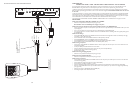
STEP 5: Connecting the Paging Amplifier
• Locate the terminals on the PCMCPU module labeled PA IN/RT and wire to the TIP and Ring (T & R) input on the Bogen paging amplifi-
er (either TPU-Series, GS-Series or Classic Series.)
• Locate the terminals on the PCMCPU module labeled PA OUT/RT and wire to COMMON and either the 25 or 70V output on the
paging amplifier.
STEP 6: Connecting 25/70V AC Speakers
• Locate the terminals on the PCMZPM module labeled ZONE A.These terminals have two connections marked + and -.Wire your
speakers for ZONE ONE to these terminals. Observe polarity (-) to common (+) to selected tap setting.
• Follow the same procedure for the terminals labeled ZONE B for ZONE TWO, and the terminals labeled ZONE C for ZONE THREE.
STEP 7: Testing your System
• Connect the power supply PCMPS2 to the PCMCPU module to either the power jack 12V DC input or wire it to the 12V DC screw
terminals, observing polarity.
• Connect the Bogen amplifier to the AC power outlet (120V AC, 60Hz).
• Set the volume on your Bogen amplifier to a 1/2 turn.
• Access the paging from the telephone system and listen (on the handset) for the confirmation tone (double beep).
• Dial 01 to access ZONE ONE and listen (on the handset and also to the speakers) for a pre-announce tone (single beep) followed by
your page (audio).
• Follow the same steps for ZONES TWO (02) and THREE (03).
• Set the Bogen amplifier to the desired volume level.
36
5