


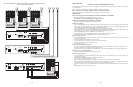


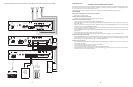
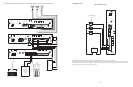

CONFIGURATION 12:
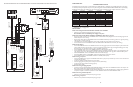
DFT120 & TAMB WIRING DIAGRAM - LOOP START TRUNK, GROUND START TRUNK, OR STATION LEVEL
In this configuration, the telephone output is connected to the Bogen Telephone Access Module model TAMB; the TAMB module is connected
to the Bogen Digital Feedback Terminator model DFT120; and the DFT120 is connected to the PCM2000 system. The TAMB module is acti-
vated by the telephone system and, at the same time, the DFT120 is activated by the TAMB’s normally open contacts. Using digital technolo-
gy, the DFT120 stores the DTMF tones and the paging audio.When the TAMB closed contacts are removed from the DFT120, the DFT120
activates the PCM2000 system also using normally open contacts, and plays the page (audio). In addition to the above equipment, you will
also need a PRSASAC power supply and two RJ11 modular boxes.
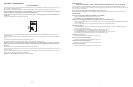
INSTALLATION:
STEP 1: Assembling Modules and Connecting the Amplifier
• Refer to step 1 on pages 5 and 17.
STEP 2: Connecting the Paging Amplifier
• Follow the same procedure described previously on page 5 or 17, step 5.
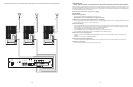
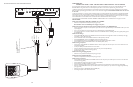
STEP 3: Connecting an Analog Line or Ground Start Trunk from the Telephone System to the TAMB
• Take the Analog Line or Ground Start trunk pair from the telephone system and wire it to the TAMB terminals T & R.
STEP 4: Connecting the TAMB Module to the DFT120
• Using a 6-pin RJ11 modular jack, connect terminals labeled PT & PR from the TAMB to the modular jack terminals R (red) and G
(green).
• Connect terminals labeled N.O. & COM from the TAMB to the modular jack terminals Y (yellow) and BK (black).
• Connect a 6-pin RJ11 modular cable from the RJ11 jack to the AUDIO IN jacks on the DFT120. Place the switch labeled DL/LS to the
DL (Dry Loop) position.
• Connect terminals labeled +24/48 & -24/48 from the TAMB to the PRSASAC power supply. Use pins 1 & 2 labeled 24V DC / 450 mA.
• Connect the DFT120 power supply (supplied with the unit) to the DFT120.
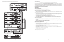
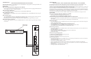
STEP 5: Connecting the DFT120 to the PCMTIM Module
• Attach a 6-pin RJ11 modular jack to the wall next to the PCM2000 unit.
• Connect terminals 3 & 4 from the DFT120 jack labeled AUDIO OUT, to the RJ11 modular jack terminals R (red) and G (green).
• Connect terminals 2 & 5 from the DFT120 jack labeled AUDIO OUT (PLAY contact) to the RJ11 modular jack terminals Y (yellow) and
BK (black).
• Connect a 6-pin RJ11 modular cable between the RJ11 modular jack and the TEL LINE RJ11 input on the PCMTIM module.
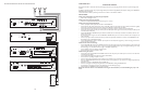
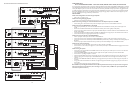
STEP 6: Switch and Control Settings
• Set the switches 1, 2 & 4 to ON (to the right) and 3 & 5 to OFF (to the left) on the TAMB.
• Set the switches 2, 3, & 7 to ON (to the right) and 1, 4, 5 & 6 to OFF (to the left) on the PCMTIM module for Paging Port Contact clo-
sure operation.
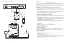
STEP 7: Testing Your System
• Connect the power supply PCMPS2 to the PCMCPU module to either the power jack 12V DC input or wire it to the 12V DC screw
terminals observing polarity.
• Connect the PCMPS2, PRSASAC, and the DFT120 power supplies and the amplifier to the AC power outlet 120V AC 60Hz.
• Set the volume on your Bogen amplifier to a half turn.
• Adjust the DFT120 AUDIO OUT volume control to 50%. (You may need to readjust this control higher or lower later, after the test.)
• Access the paging from the telephone system.The RECORD LED on the DFT120 must be lit showing that the DFT120 is already
recording.
• Dial 01 to record ZONE ONE DTMF tone followed by a test page. (Notice that you will not hear audio coming from the speakers at
this point.)
• Hang-up the handset.The PLAY LED on the DFT120 must light showing that the DFT120 is playing the page and you must be able to
hear the page.
• If the page is too low, adjust the control for optimal operation.
Note: Unlike the previous Digital Feedback Terminator (DFT30), the DFT120 will accept a Loop Start Trunk or Page Port
directly connected to the unit.Therefore, when connecting to a Loop Start Trunk, a TAMB is not required. (See DFT120
manual for complete instructions.)
14
27
PCM
TIM
POWER
TONE
VOLUME
BGM SRC
VOLUME
GND ST
IN
RT
BGM
SRC
NIGHT
RING
TEL
LINE
OVER
RIDE
NC
COM
NO
NC
COM
NO
RLY
ONE
RLY
TWO
S1
S2
S3
S4
S5
S6
S7
TEL
INT
SEL
0 1
POWER
- 1.5A
OUT
RT
GND
AUX
GND
S1
S2
S3
S4
0 1
SYS
ID
RUN
PROGRAM
DATA
LINK
12 VDC
1.5A
-
IN
RT
RT
IN
RT
IN
EM/SC
+ 12VDC
BOGEN
PA
LPBGM
PA
HPBGM
+
POWER
RD COM
+
-
RD A
RD B
ZONE A
ZONE B
ZONE C
OFF ON
TALKBACK
RT
IN
RD C
LOCAL
BGM
ZONE A
+
-
ZONE B
+
-
ZONE C
LPBGM
VOLUME
LO PWR
HI PWR
OUTPUT
BGM
OUT IN
PCM
ZPM
PCM
CPU
RT70V COM
BOGEN PAGING
AMPLIFIER
POWER
RD COM
+
-
RD A
RD B
ZONE A
ZONE B
ZONE C
OFF ON
TALKBACK
RT
IN
RD C
LOCAL
BGM
ZONE A
+
-
ZONE B
+
-
ZONE C
LPBGM
VOLUME
LO PWR
HI PWR
BGM
OUT IN
ZPM
POWER
RD COM
+
-
RD A
RD B
ZONE A
ZONE B
ZONE C
OFF ON
TALKBACK
RT
IN
RD C
LOCAL
BGM
ZONE A
+
-
ZONE B
+
-
ZONE C
LPBGM
VOLUME
LO PWR
HI PWR
OUTPUT
BGM
OUT IN
PCM
ZPM
POWER
- 1.5A
OUT
RT
GND
AUX
GND
S1
S2
S3
S4
0 1
SYS
ID
RUN
PROGRAM
DATA
LINK
12 VDC
1.5A
-
IN
RT
RT
IN
RT
IN
EM/SC
+ 12VDC
BOGEN
PA
LPBGM
PA
HPBGM
+
PCM
CPU
POWER
RD COM
+
-
RD A
RD B
ZONE A
ZONE B
ZONE C
OFF ON
TALKBACK
RT
IN
RD C
LOCAL
BGM
ZONE A
+
-
ZONE B
+
-
ZONE C
LPBGM
VOLUME
LO PWR
HI PWR
OUTPUT
BGM
OUT IN
PCM
ZPM
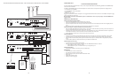
SATELLITE ASSEMBLY #1
MASTER ASSEMBLY
PCM
ZONE A
ZONE B
ZONE C
GLOBL BGM
ZONE A
ZONE B
ZONE C
GLOBL BGM
ZONE A
ZONE B
ZONE C
GLOBL BGM
ZONE A
ZONE B
ZONE C
GLOBL BGM
OUTPUT
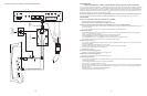
SETUP FOR CONFIGURATION 6:EXTENDED PAGING SYSTEM