


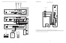


CONFIGURATION 11:
MICROPHONE OVERRIDE
Microphone Override is a feature that lets the system designer take priority over all paging functions and make a system-wide page to all
speakers.
In addition to the PCM modules, setup requires a Bogen VAR1 (voice-activated relay), PRS40C (12V DC power supply) and an MBS1000 or
DDU250 (desktop microphone).
The Override feature includes a quad beep pre-announce tone which can be enabled or inhibited.
INSTALLATION:
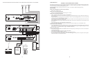
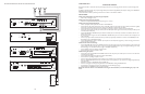
STEP 1: Assembling Modules and Connecting the Amplifier
• Refer to step 1 on pages 5 and 17.
STEP 2: Connecting the Paging Amplifier
• Follow the same procedure described previously on page 5 or 17, step 5.
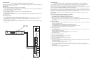
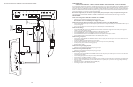
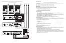
STEP 3: Connecting Optional Equipment
• Attach a 6-pin RJ11 modular jack to the wall next to the PCM2000 unit.
• Connect the first audio output terminal from the top of the VAR1 (right screw terminals) to the RJ11 modular jack terminal Y (yellow).
Connect the second audio output terminal from the top of the VAR1 to the N.O. contact of the VAR1.
• Connect the fifth screw terminal from the top of the VAR1 (see drawing) to the RJ11 modular jack terminal BK (black).
• Connect the relay terminals (normally open contacts) from the VAR1 (two bottom right screw terminals) to the RJ11 modular jack ter-
minals W (white) and BL (blue).
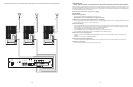
• Connect the MBS1000 or DDU250 microphone leads to the VAR1 (left screw terminals): red to third screw, black to fifth screw, and
shield to fourth screw.
• Do not use the white and green wires from the MBS1000 or DDU250 unless you want to use them instead of the normally open con-
tacts on the VAR1.
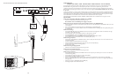
• Connect a 6-pin RJ11 modular cable between the RJ11 modular jack (previously attached to the wall next to the PCM2000) and the
Override RJ11 input on the PCMTIM module.
• Connect the PRS40C power supply to the VAR1 (two top left screw terminals) observing polarity or use the mini-plug and connect it
into the mini-jack at the bottom.
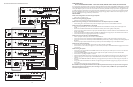
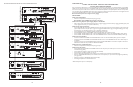
STEP 4: Switch and Control Settings
• Set the TEL-INT-SEL DIP switches on the PCMTIM module to match the paging output access from the telephone system based on the
type of telephone interface used. (See step 3 on page 5 if using Page Port Contact Closure; page 7 for Page Port VOX; page 9 for Loop
Start Trunk; page 11 for Ground Start Trunk; or page 13 for Station Level/Centrex.)
• Set the Line/MIC switch on the VAR1 to the MIC position.
• Set the Mic volume control on the VAR1 at 50%.
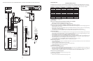
STEP 5: Testing Your System
• Connect the power supply PCMPS2 to the PCMCPU module to either the power jack 12V DC input or wire it to the 12V DC screw
terminals observing polarity.
• Connect the Bogen amplifier to the AC power outlet (120V AC 60Hz).
• Set the volume on your Bogen amplifier a half turn.
• Access the paging from the telephone system and listen (on the handset) for the confirmation tone (double beep).
• Dial 01 to access ZONE ONE and listen (on the handset and also to the speakers) for a pre-announce tone (single beep) followed by
your page (audio).
• Follow the same steps for ZONES TWO (02) and THREE (03).
• Access the emergency override by pressing the talk bar on the MBS1000 or sliding the DDU250 switch.
• You should hear a quad beep pre-announce tone followed by your all-call/emergency page.
• Adjust the VAR1 and PCM2000 controls for optimal operation.
NOTE: You will not be able to access individual zones using the Override feature, it is for All-Call Emergency only to all
zones.
16
25
PCM
TIM
POWER
TONE
VOLUME
BGM SRC
VOLUME
GND ST
IN
RT
BGM
SRC
NIGHT
RING
TEL
LINE
OVER
RIDE
NC
COM
NO
NC
COM
NO
RLY
ONE
RLY
TWO
S1
S2
S3
S4
S5
S6
S7
TEL
INT
SEL
0 1
POWER
- 1.5 A
OUT
RT
GND
AUX
GND
S1
S2
S3
S4
0 1
SYS
ID
RUN
PROGRAM
DATA
LINK
12 VDC
1.5A
-
IN
RT
RT
IN
RT
IN
EM/SC
+ 12VDC
BOGEN
PA
LPBGM
PA
HPBGM
+
POWER
RD COM
+
-
RD A
RD B
ZONE A
ZONE B
ZONE C
OFF ON
TALKBACK
RT
IN
RD C
LOCAL
BGM
ZONE A
+
-
ZONE B
+
-
ZONE C
LPBGM
VOLUME
LO PWR
HI PWR
OUTPUT
BGM
OUT IN
PCM
ZPM
PCM
CPU
+
-
PCM PS2
R T 70V COM
BOGEN PAGING
AMPLIFIER
PCM
TBM
POWER
VOLUME
TALKBACK
DELAY
OUT
RT
IN
RT
PA
PA
NOISE
REDUCTION
ON
OFF
ZONE A
ZONE B
ZONE C
GLOBL BGM
ZONE C
ZONE B
ZONE A
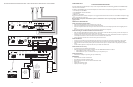
SETUP FOR CONFIGURATION 7:TWO-WAY TALK BACK PAGING SYSTEM