


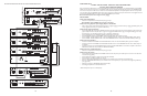
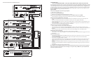

CONFIGURATION 14:
DTMF MICROPHONE ZONE PAGING
This section will describe the configuration for the use of a Shure microphone Model 885TT with DTMF dialing capabilities and the MODULINK five-
conductor coil-cord model ALM-
1
.
In addition to the PCM2000 system and associated amplifiers, the model numbers and components required for this configuration are:
1- Shure Microphone model 885TT
1- Shure MODULINK coil cord model ALM-1
1- XLR connector
1- 680 ohms ¼-watt resistor
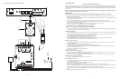
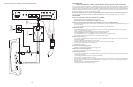
Paging with a DTMF Shure condenser microphone is a non-programmable feature that lets the caller use a Shure 885TT microphone to page
one-way to specific zones or all zones.
Note:The Shure microphone model 885TT requires a modification in order to operate properly with the PCM2000 zone
paging modules.
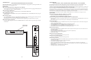
SHURE 885TT MODIFICATION:
STEP 1: Disassembling the Microphone
• Remove the cable, if attached, to the microphone using a paper clip.
• Remove the four Phillips-head screws from the back of the microphone.
• Hold the microphone with its back toward you and the cable connector down, and carefully separate the case back slightly from the
front.
• Pivot the case back to the right taking care not to damage any internal leads or components.
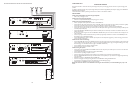
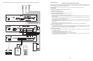
STEP 2: Detaching the Case Back and Rear Printed Circuit Board
• With the partially disassembled microphone face down on a flat surface and with the cable entry toward you, locate the multi-pin con-
nector on the left side between the center board and the rear board.
• Carefully pry the rear board away from the connector on the centerboard.You may need a small flathead screwdriver to separate the
terminal pins connected to the rear board and the connector attached to the center board.
• Lift the microphone case back and the rear board away from the center board.
STEP 3: Modification
• Locate pin 5 on the solder side of the J303 phone jack (cable entry) and cut the trace around pin 5, disconnecting it from ground.
• Locate the black wire connected from the microphone switch to the first printed circuit board and unsolder it from the board.
• Solder the black wire disconnected previously from the first P.C. board to pin 5 on the soldered side of the J303 phone jack (cable
entry).
• Locate transistor Q303 on the component side and clip or unsolder the collector lead.
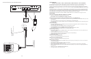
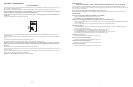
STEP 4: XLR Connector Setup
• An XLR connector (not included) is recommended.
• Solder the XLR connector to the Shure microphone coil cord MODULINK model ALM-1 as follows:
• Solder a 680-ohm resistor across pins 1 and 2
• Solder-shielded wire to pin 1, red and black wires to pin 2, and yellow to pin 3.
STEP 5: Reassembling
• Reassemble the microphone by reversing the steps of disassembly.
OPERATION:
• Connect the XLR connector to MIC socket.
• Press and keep pressed the microphone switch.
• Dial the two digits to access the zone desired or dial 00 for all-call.
• Make a page.
• Release the microphone switch.
• Repeat procedure to page again.
10
31
PCM
TIM
POWER
TONE
VOLUME
BGM SRC
VOLUME
GND ST
IN
RT
BGM
SRC
NIGHT
RING
TEL
LINE
OVER
RIDE
NC
COM
NO
NC
COM
NO
RLY
ONE
RLY
TWO
S1
S2
S3
S4
S5
S6
S7
TEL
INT
SEL
0 1
POWER
- 1.5A
OUT
RT
GND
AUX
GND
S1
S2
S3
S4
0 1
SYS
ID
RUN
PROGRAM
DATA
LINK
12 VDC
1.5A
-
IN
RT
RT
IN
RT
IN
EM/SC
+ 12VDC
BOGEN
PA
LPBGM
PA
HPBGM
+
POWER
RD COM
+
-
RD A
RD B
ZONE A
ZONE B
ZONE C
OFF ON
TALKBACK
RT
IN
RD C
LOCAL
BGM
ZONE A
+
-
ZONE B
+
-
ZONE C
LPBGM
VOLUME
LO PWR
HI PWR
OUTPUT
BGM
OUT IN
PCM
ZPM
PCM
CPU
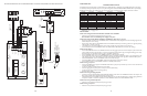
PBX
GROUND
START
TRUNK
T
R
1 - Not used
2 - Not used
3 - Ring (Negative)
4 - Tip (Positive)
5 - Not used
6 - Not used
+
-
PCM PS2
RT
70V COM
BOGEN PAGING
AMPLIFIER
S1
S2
S3
S4
S5
S6
S7
TEL
INT
SEL
0 1
PBX Ground
ZONE A
ZONE B
ZONE C
GLOBL BGM
ZONE C
ZONE B
ZONE A
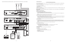
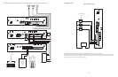
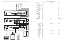
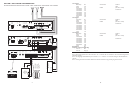
SETUP FOR CONFIGURATION 4: GROUND START TRUNK - 3-ZONE - ONE-WAY PAGING - SINGLE AMPLIFIER - 25/70V AC SPEAKERS