142
10
10
AUXILIARY PTO
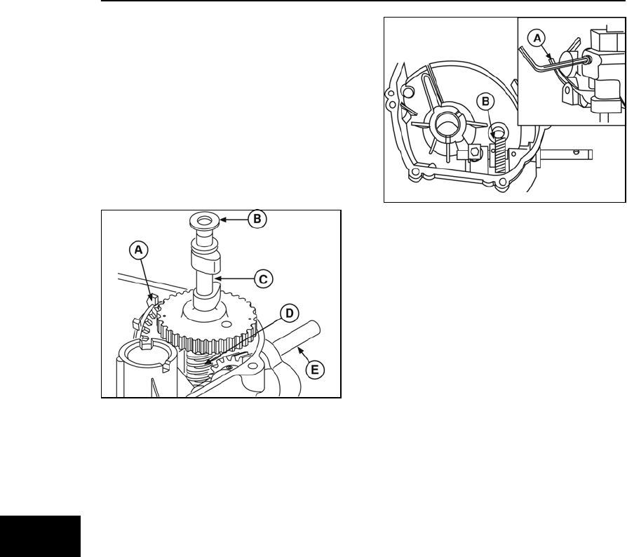
Some models of the vertical shaft 110000 and
120000 engines were equipped with an auxiliary
PTO shaft. The auxiliary PTO shaft (E, Figure
23) extends through the side of the sump,
perpendicular to the crankshaft. Rotation can be
either clockwise or counterclockwise, as viewed
from the end of the shaft. The oil slinger (A),
camshaft (C), and worm gear (D) are pre-
assembled and must be serviced as a set.
NOTE: The clockwise system requires a thrust
washer (B) installed at the upper camshaft
journal. The counterclockwise system requires
the thrust washer be installed at the lower
journal, under the worm gear.
Figure 23
Remove Auxiliary PTO Drive Shaft
1. Remove all rust and burrs from
crankshaft, then remove sump.
2. To remove auxiliary PTO shaft from sump,
remove Allen screw (A, Figure 24) from
bottom of sump. The slinger, camshaft,
and worm gear assembly will remain in the
cylinder.
Figure 24
3. With a 3/16” pin punch, drive the roll pin in
the bevel gear (B) through the allen screw
hole.
4. Remove screw and PTO shaft stop then
slide out PTO shaft.
Inspection
Inspect all parts for evidence of wear or damage.
If replacement is required, ensure the correct
rotation set (clockwise or counterclockwise) is
chosen from the Illustrated Parts List.
Assemble Auxiliary PTO Drive Shaft
1. Place drive shaft in sump and push shaft
through bevel gear.
2. Line up holes in bevel gear and drive
shaft. Install new roll pin until it is centered
in gear.
3. Place shaft stop in groove of drive shaft
and install screw. Torque to values listed
in Section 12 - Engine Specifications.
4. Install allen screw in bottom of sump and
torque to values listed in Section 12 -
Engine Specifications.
5. Rotate assembly by hand to check for
binding.
6. Using new gasket, install sump to cylinder
according to instructions provided earlier
in this section.


