


35
2
2
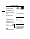
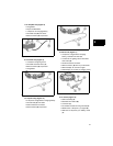
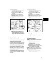
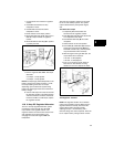
Test Alternator Output
1. Insert RED test lead (A, Figure 19) into
the V Ω receptacle in the meter.
2. Insert BLACK test lead (B) into COM
receptacle.
3. Rotate selector to AC Volts position.
4. Attach RED test lead clip to AC output
terminal (C).
5. Attach BLACK test lead clip to engine
ground.
Figure 19
6. With engine running at 3600 RPM, AC
output should be no less than 14 Volts.
• If NO or LOW output is found, replace the
stator.
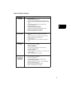
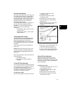
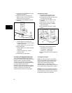
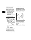
Dual Circuit Alternator
Dual Circuit alternators use a polarized plug with
two pins. One pin provides DC current for
charging the battery, the second pin is an
independent AC circuit for headlights.
Current for lights is available when the engine is
running. The output varies, so brightness of the
lights changes with engine speed. 12 Volt lights
with a total rating of 60 to 100 watts may be
used. With lights rated at 70 watts, the voltage
rises from 8 Volts @ 2400 RPM to 12 Volts at
3600 RPM. Since the battery is not used for the
lights, the lights are available even if the battery
is disconnected or removed.
Current for the DC side of the alternator is
unregulated and is rated at 3 Amps. The output
rises from 2 Amps @ 2400 RPM to 3 Amps @
3600 RPM.
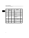
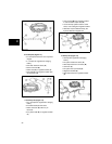
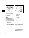
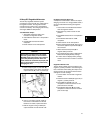
Test Alternator Output-AC
1. Insert RED test lead (A, Figure 20) into
the V Ω receptacle in the meter.
2. Insert BLACK test lead (B) into COM
receptacle.
3. Rotate selector to AC Volts position.
4. Attach RED test lead clip to AC output pin
(C).
5. Attach BLACK test lead clip to engine
ground.
Figure 20
6. With engine running at 3600 RPM, AC
output should be no less than 14 Volts.
• If NO or LOW output is found, replace the
stator.
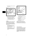
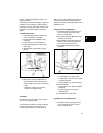
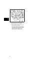
Test Alternator Output-DC
NOTE: The battery MUST be in good condition
to perform this test.
1. Insert RED test lead into 10 Amp
receptacle in meter.
2. Insert BLACK test lead into COM
receptacle in meter.
3. Rotate selector to DC Amps position.
4. Attach RED test lead clip (A, Figure 21) to
DC output pin (F) in connector (D).
NOTE: The raised rib on the connector or the
RED wire indicates the DC output pin side. The
AC pin is not used for the test.
5. Attach BLACK test lead clip (B) to the
positive (+) battery terminal.