


32
2
2
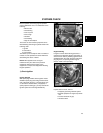
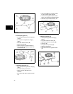
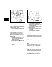
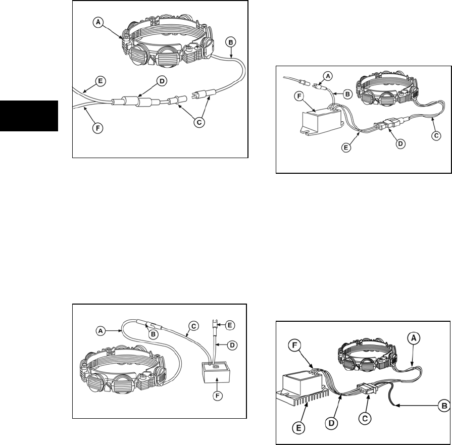
Figure 12
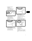
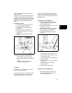
6. 5/9 Amp DC (Figure 13)
• 5 or 9 Amp DC based on size of flywheel
magnet
• 5 - 9 Amps DC regulated for charging
battery
• One black lead from stator (A)
• Green connector (B)
• Yellow lead (C) to regulator-rectifier (F)
• One lead (D) from regulator-rectifier with
red connector (E)
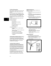
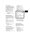
Figure 13
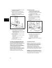
7. 10/16 Amp DC (Figure 14)
• 10 or 16 Amps DC regulated for charging
battery
• Two black leads (C) from stator
• Yellow connector (D) with two pin
terminals
• Two yellow leads (E) to regulator-rectifier
(F)
• One red lead (B) from regulator-rectifier
to red connector output lead (A)
• 10 and 16 Amp systems use the same
stator, color coding and regulator-rectifier
• Alternator output is determined by the
flywheel alternator magnet size
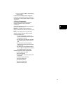
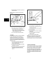
Figure 14
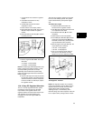
8. 20 Amp DC (Figure 15)
• 20 Amps DC regulated for charging
battery
• Two yellow leads from stator (A)
• Red output lead from connector (B)
• Connector (C)
• Two yellow AC input leads (D)
• Regulator Rectifier (E)
• Red output lead from regulator-rectifier
(F)
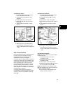
Figure 15