


Page 15
SERVICE (cont.)
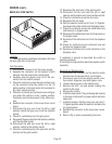
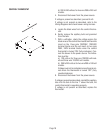
BREW SELECTOR SWITCH
Location:
The brew selector switches are located in the front
left and right side of the hood.
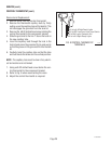
Test Procedure:
1. Disconnect the brewer from the power supply.
2. Separate the connector on the selector switch
harness from the brew timer circuit board.
3. Carefully slide the plastic cover off of the con-
nector from the switch harness.
4. Check for continuity across the pink and tan wires
on the connector when the switch is in the 1/2
gallon position. Continuity must not be present in
any other switch position.
5. Check for continuity across the pink wire and gray
wire when the switch is in the 1 gallon position.
Continuity must not be present in any other posi-
tion.
6. Reattach the connector to the brew timer circuit
board.
7. Disconnect the gray wire from the left or right
selector switch and gray wire from the interface
socket.
8. Check for continuity across the gray wires.
9. Reconnect the gray wires from the selector switches
and the interface socket.
10. Disconnect the pink wire from the left or right
selector switch to the grinder switch.
11. Check for continuity across the pink wire and the
terminal on the grind switch.
12. Reconnect the pink wire to the grind switch.
13. Disconnect the tan wire from the left or right
selector switch and tan wire from interface socket.
14. Check for continuity across the tan wires.
15. Reconnect the tan wires.
16. With the selector switch set at 1 and 1-1/2 gallon,
disconnect the white/violet from the bypass valve.
17. Check for continuity across the white/violet wire
and terminal on bypass valve.
18. Reconnect the white/violet wire to the terminal on
the bypass valve.
19. Disconnect the white/red wire from the dispense
valve.
20. Check for continuity across white/red wire and
terminal on dispense valve.
21. Reconnect white/red wire to the terminal on the
dispense valve.
If continuity is present as described the switch is
operating properly.
If continuity is not present as described replace switch
assembly.
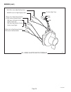
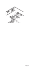
Removal and Replacement:
1. Disconnect the connector on the selector switch
harness from the brewer timer circuit board.
2. Disconnect wires from the selector switch, inter-
face socket, dispense valve and bypass valve.
3. Loosen the set screw on the switch knob.
4. Remove the 9/16" nut and washer holding the
switch to the hood.
5. Remove the switch.
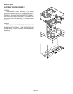
6. Install the new switch. The positioning tab must be
in the hole in the hood for proper switch and knob
alignment.
7. Install the knob so that the arrow lines up in the 1-
1/2 gallon position when the switch is turned to the
full right position.
8. Reattach the connector to the brew timer circuit
board.
9. Refer to Fig. 4 when reconnecting the wires.
P775
S
T
A
R
T
O
N
/
W
A
R
M
E
R
S
E
L
E
CT
O
R
R
E
A
D
Y
R
E
A
D
Y