


Page 25
SERVICE (cont.)
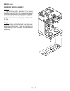
ELECTRONIC CONTROLS (cont.)
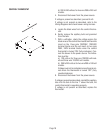
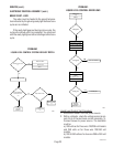
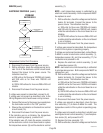
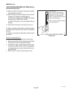
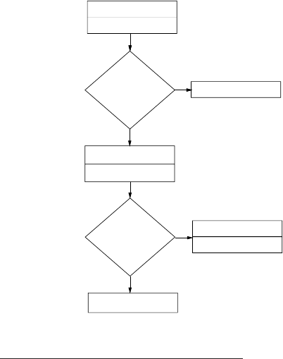
PROBLEM:
WATER BOILS
YES
NO
NO
NO
NO
REPLACE CONTROL
ASSEMBLY (1)
REPLACE TRIAC (17)
CHECK FOR SPLIT
TANK HEATER (5)
DRAIN CUP (4)
RETRY
LED (13)(15) ON
WHILE BOILING
DISCONNECT BLUE WIRE
FROM CONTROL BOARD PIN #7
RETRY
STILL BOILING
?
REPLACE CONTROL
ASSEMBLY (1)
assembly (1).
NOTE - each temperature sensor is calibrated to an
electronic control assembly. Both components MUST
be replaced as a set.
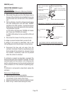
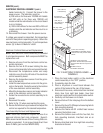
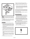
7. With a voltmeter, check the voltage across the tank
heater (5) terminals. Connect the brewer to the
power source. The indication must be:
a.) 208 volts for three wire 120/208 volt models
and 240 volts for three wire 120/240 volt models
while the red indicator on the circuit board is on or
blinking.
b.) 200 to 240 volts ac for two wire 200 or 240 volt
models while the red indicator on the circuit board
is on or blinking.
8. Disconnect the brewer from the power source.
If voltage was present as described, the temperature
control of the system is operating properly.
If voltage was not present as described, contact Bunn-
O-Matic to order an electronic control assembly (1),
temperature sensor (8), and triac assembly (17) for
revaluation and proceed to #9.
9. Replace the electronic control assembly (1) and
temperature sensor (8).
NOTE - each electronic control assembly is calibrated
to a temperature sensor. Both components MUST be
replaced as a set.
10. With a voltmeter, check the voltage across the tank
heater terminals (5). Connect the brewer to the
power source. The indication must be:
a.) 208 volts ac for three wire 120/208 volt models
and 240 volt ac for three wire 120/240 volt models
while the red indicator on the circuit board is on or
blinking.
b.) 200 to 240 volts ac for two wire 200 or 240 volt
models while the red indicator on the circuit board
is on or blinking.
11. Disconnect the brewer from the power source.
If voltage was present as described, return the new
triac assembly (17) to Bunn-O-Matic for credit. The
temperature control of the system is operating prop-
erly.
If voltage was not present as described, reinstall your
existing electronic control assembly (1) and tempera-
ture sensor (8), and proceed to #12.
12. Replace the triac assembly (17).
13. With a voltmeter, check the voltage across the tank
P811
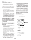
Temperature Control Test Procedure
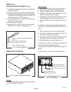
1. Disconnect the brewer from the power source.
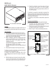
2. With a voltmeter, check the voltage across termi-
nals 3 & 4 of the electronic control circuit board.
Connect the brewer to the power source. The
indication must be:
a.) 208 volts ac for three wire 120/208 volt models
and 240 volts ac for three wire 120/240 volt
models.
b.) 200 to 240 volts ac for two wire 200 or 240 volt
models.
3. Disconnect the brewer from the power source.
If voltage was present as described, proceed to #4.
If voltage was not present as described, refer to the
Wiring Diagrams
and check brewer wiring harness.
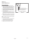
4. Connect the brewer to the power source and place
the tank heater switch in the “ON” position.
5. Observe the red indicator on the electronic control
circuit board (15).
6. Disconnect the brewer from the power source.
If the indicator was on or blinking, the temperature
sensor is operating properly, proceed to #7.
If the indicator was off, check the sensor connection
on the electronic control circuit board and/or replace
the temperature sensor (8) and the electronic control
27040 041100