Page 19
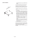
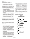
b.) 200 to 240 volts ac for two wire 200 or 240 volt
models.
4. Disconnect the brewer from the power source.
If voltage is present as described, proceed to #5.
If voltage is not present as described, refer to the
Wiring Diagrams
and check brewer wiring harness.
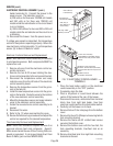
5. Locate the black wires from the control thermo-
stat.
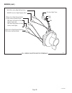
6. Gently remove the capillary bulb and grommet
from the tank.
7. With a voltmeter, check the voltage across the
black wires of the control thermostat and the white
insert on the three pole 120/208V, 120/240V
terminal blocks and the red insert on two pole
200V, 240V terminal blocks when the control
thermostat is turned "ON" (fully clockwise). Con-
nect the brewer to the power source. The indica-
tion must be:
a.) 120 volts ac for three wire 120/208 volt mod-
els and three wire 120/240 volt models.
b.) 200 to 240 volts ac for two wire 200 or 240 volt
models.
Voltage must not be indicated across these termi-
nals when the thermostat is turned "OFF" (fully
counterclockwise).
8. Disconnect the brewer from the power source.
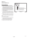
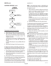
If voltage is present as described, reinstall the capillary
tube into the tank to the line 7" above the bulb, the
control thermostat is operating properly.
If voltage is not present as described, replace the
thermostat.
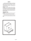
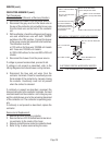
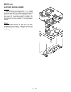
CONTROL THERMOSTAT


