


Page 43
SERVICE (cont.)
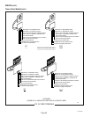
WARMER ELEMENTS
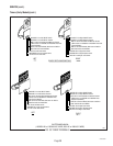
WHI/VIO to Right Timer TL1
WHI to Terminal Block (White Insert on
Three Pole Terminal Blocks or Red Insert
on Two Pole Terminal Blocks)
WHI or Red to Left Warmer Element
RIGHT WARMER
ELEMENT
LEFT WARMER
ELEMENT
WHI to Terminal Block (White Insert
on Three Pole Terminal Blocks or
Red Insert on Two Pole Terminal Blocks)
WHI or Red to Right Warmer Element
WHI/RED to Left Timer TL1
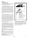
!
CAUTION
H
OT
W
AT
ER
.
M
IN
U
T
E
S
B
U
N
N
-
O-
M
A
T
IC
P
/
N
2
6
2
0
-
1
2
0
V
A
C
.
M
IN
U
T
E
S
B
U
N
N
-
O-
M
A
T
I
C
P
/
N
2
6
2
0
-
1
2
0
V
A
C
ST
A
RT O
N
/
W
ARM
E
R
S
EL
EC
T
O
R
R
EAD
Y
R
E
A
D
Y
O
N
/
W
A
RM
E
R
S
T
A
RT
1
1
⁄2
g
a
l
1
g
a
l
1
⁄2
g
a
l
S
EL
E
C
T
O
R
1
1
⁄
2
g
a
l
1
g
a
l
1
⁄
2
g
a
l
C
A
U
T
IO
N
:
W
A
R
M
E
R
S
A
N
D
S
UR
F
A
C
E
S
A
R
E
HO
T
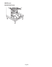
Location:
The warmer elements are located in the base of the
brewer under the warmer plate.
Test Procedures:
1. Disconnect the brewer from the power source.
2. Using the white wire in the terminal block and the
white/red wire to left warmer or the white/violet
wire to right warmer check the voltage. With a
voltmeter, check voltage across the white and
white/red wire or the white wire and white/violet
wire with the "ON/OFF" switch in the "ON" position.
The indication must be 120 volts ac for three wire
120/208 volt models and three wire 120/240 volt
models.
3. With a voltmeter, check the voltage across the red
wire and white/red wire or red wire and white/
violet wire with the "ON/OFF" switch in the "ON"
position. The indication must be 200 to 240 volts
ac for two wire 200 or 240 volt models.
4. Disconnect the brewer from the power source.
If voltage is present as described, proceed to #5.
If voltage is not present as described, refer to the
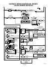
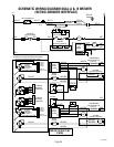
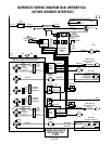
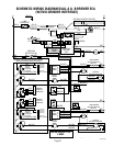
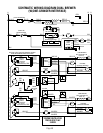
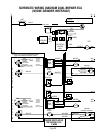
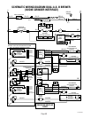
Wiring Diagrams
and check brewer wiring harness.
5. Check the continuity across the two terminals on
the warmer element.
If continuity is present as described, reconnect the
white or red and white/red wires on the left warmer
element or the white or red and white/violet wires on
the right warmer element.
If continuity is not present as described, replace the
warmer element.
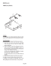
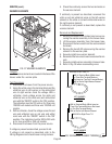
Removal and Replacement:
1. Remove the three #4-40 slotted head screws se-
curing the warmer assembly to the brewer base.
2. Lift the warmer assembly from the brewer base.
3. Disconnect the two wires from the warm element
terminals.
4. Remove the two #8-32 nuts securing the warmer
element to the warmer plate.
5. Securely install new warmer element.
6. Reconnect the two wires to warmer element termi-
nals.
7. Securely install warmer assembly in brewer base.
8. Refer to Fig. 38 when reconnecting wires.
P796
P807
27040 032201
FIG. 38 WARMER ELEMENT TERMINALS
FIG. 37 WARMER ELEMENTS