


Page 29
SERVICE (cont.)
LEVEL CONTROL BOARD AND LEVEL PROBE (Electro/
mechanical only) (cont.)
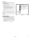
15. Move the probe's flat end to the brewer housing.
The indication must be 0.
16. Move the probe's flat end away from the brewer
housing. The indication should again be:
a.) 120 volts ac for three wire 120/208 volt models
and three wire 120/240 volt models.
b.) 200 to 240 volts ac for two wire 200 or 240 volt
models.
17. Disconnect the brewer from the power source.
If voltage is present as described, reinstall the probe,
the level control board and level probe are operating
properly.
If voltage is not present as described, check the pink
probe wire.
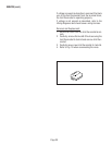
Removal and Replacement:
1. Remove all wires from the level control board.
2. Remove two #8-32 slotted head screws holding
level control board to component bracket.
3. Install the new level control board to the compo-
nent bracket. Make certain that the lockwashers
are between the level control board and the com-
ponent bracket.
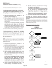
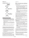
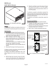
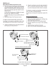
4. Refer to Fig. 17 when reconnecting the wires.
P789
T4 PNK to Probe
T3 WHI to Terminal Block (White
Insert on 120V Two Wire, 120/208V
or 120/240V Three Wire Brewers)
T3 RED to Terminal Block (Red Insert
on 200V or 240V Brewers)
T2 BLU to Overflow Protection Switch
T1 VIO to Solenoid Coil
FIG. 17 LIQUID LEVEL CONTROL BOARD
TERMINALS
27040 032201