


Page 18
SERVICE (cont.)
CONTACTOR ASSEMBLY (cont.)
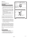
P778
27040 032201
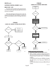
Test Procedures :
Electronic Control (Brewers w/Recovery Booster)
1. Disconnect the brewer from the power source.
2. Disconnect the gray wire from the black wire on
the rear of the contactor coil and white /brown wire
from the black wire on the front of the contactor
coil.
3. With a voltmeter, check the voltage across the gray
wire and white/brown wire with both "ON/OFF"
switches in the "ON" position. Connect the brewer
to the power source and press both start switches.
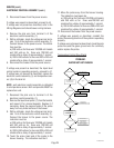
The indication must be:
a.) 120 volts ac for three wire 120/208 volt models
and three wire 120/240 volt models.
b.) 200 to 240 volts ac for two wire 200 or 240 volt
models.
4. Disconnect the brewer from the power source.
If voltage is present as described, proceed to #5.
If voltage is not present as described, refer to the
Wiring Diagrams
and check brewer wiring harness.
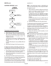
5. Disconnect the blue and red wires from the
contactor terminals. Check for countinuity across
the terminals of the contactor by manualy closing
the contacts. Countinuity must not be present
when the contact is released.
If continuity is present as described, reconnect the
blue and red wires to the contactor terminals. Connect
one black lead from the contactor coil to the gray wire
and the white/brown wire to the remaining black lead
of the contactor coil. The contactor is operating prop-
erly.
If continuity is not present as described, replace the
contactor.
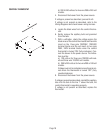
Removal and Replacement:
1. Remove all wires from the contactor.
2. Remove the two #10-32 slotted head screw secur-
ing contactor to the inside of the hood.
3. Securely install the new contactor inside the hood.
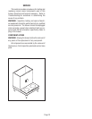
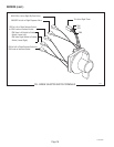
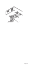
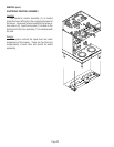
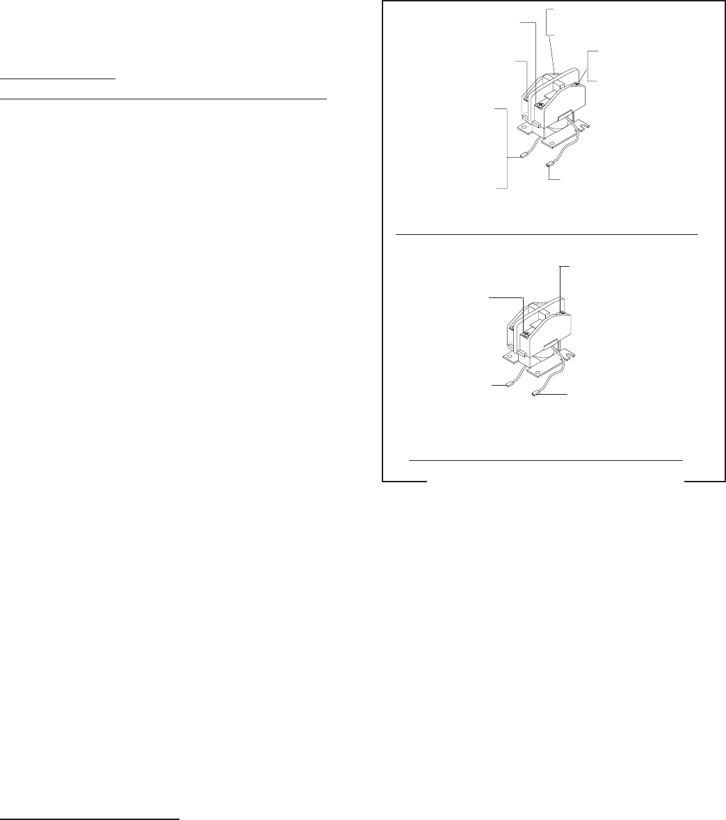
4. Refer to Fig. 6 when reconnecting the wires.
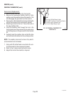
FIG. 6 CONTACTOR TERMINALS
MECHANICAL THERMOSTAT W/RECOVERY BOOSTER
ELECTRONIC CONTROL W/RECOVERY BOOSTER
BLK T2 to Left Tank Heater
BLK T2 to Right Tank Heater
RED T1 to Left Tank Heater
RED T1 to Right Tank Heater
BLK to BLK Lead from Thermostat
RED L1 to Terminal Block
(Red Insert)
BLK L2 to Terminal Block
(Black Insert)
BLK to WHI Lead from the
Three Pole 120/208V or
120/240V Terminal Block
BLK to RED Lead from the
Two Pole 200V or 240V
Terminal Block
RED T1 to Terminal Block (Red
Insert)
BLU L1 to Left Tank
Heater
BLK to GRY on Relay
BLK to WHI/BRN to Left
Dispense Valve