


Page 26
SERVICE (cont.)
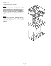
ELECTRONIC CONTROL ASSEMBLY (cont.)
O
N
CAUTION
!
F
ailu
re
To
Com
p
ly
V
o
id
s
W
a
rra
n
t
y!
Ho
t W
a
te
r
S
y
s
te
m
s
– W
a
te
r T
a
n
k
W
ill F
ill
A
u
to
m
a
tic
a
lly
W
h
e
n
U
n
it Is
C
o
n
n
e
c
t
e
d
T
o
P
o
w
e
r!
Coffe
e
Brewers
– F
ill T
h
e
W
a
te
r T
a
n
k In
A
c
c
o
rd
a
n
c
e
W
ith
T
h
e
In
s
ta
ll
a
tio
n
In
stru
ctio
n
s
!
D
O
N
O
T
T
u
rn
On
T
h
e T
a
n
k
Heate
r
Sw
itch
U
ntil W
a
te
r C
o
m
es F
ro
m
Open
ed
F
au
cet!
H
A
Z
A
RD
O
U
S
V
O
L
TA
GE
D
I
SC
O
NN
E
CT FR
O
M
P
O
W
ER
S
O
URC
E
B
E
F
O
RE
RE
M
O
V
I
N
G
!
W
A
R
NIN
G
OFF
N
O
N
CAUTION
!
F
a
ilu
re
To
Co
m
p
ly
V
o
id
s
W
arr
a
n
ty
!
Ho
t W
a
ter
Sy
s
te
m
s
– W
a
te
r T
a
n
k W
ill F
il
l
A
u
to
m
a
tic
a
lly W
h
e
n
U
n
it Is C
o
n
ne
cte
d T
o
P
o
w
e
r!
Coffe
e
Brew
e
rs
– F
ill T
h
e
W
ate
r T
an
k
In
A
c
c
o
rd
a
n
c
e
W
ith
T
h
e
In
sta
lla
t
io
n
In
s
tru
ctio
n
s
!
D
O
N
O
T
T
urn
On
T
he T
an
k
Heater Sw
itch
U
ntil W
a
ter C
om
e
s F
rom
Opened
F
auc
et!
HAZARDOUS
VOLTAGE
DISCONNECT FROM
POWER SOURCE
BEFORE REM
OVING!
WARNING
STOP
READ NOTICE
O
P1
P2
P3
P4
OFF
O
N
STOP
READ NOTICE
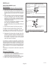
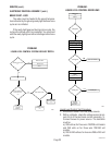
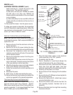
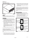
heater terminals (5). Connect the brewer to the
power source. The indication must be:
a.) 208 volts ac for three wire 120/208 volt models
and 240 volts ac for three wire 120/240 volt
models while the red indicator on the circuit board
is on or blinking.
b.) 200 to 240 volts ac for two wire 200 or 240 volt
models while the red indicator on the circuit is on
or blinking.
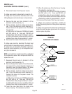
14. Disconnect the brewer from the power source.
If voltage was present as described, the temperature
control of the system is operating properly. Return the
new electronic control assembly (1) and temperature
sensor (8) to Bunn-O-Matic for credit.
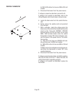
Electronic Controls Removal and Replacement
NOTE - each electronic control assembly is calibrated
to a temperature sensor. Both components MUST be
replaced as a set.
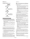
1. Remove all wires from the electronic control as-
sembly terminals.
2. Remove the two 8-32 screws holding the elec-
tronic control assembly to the component bracket.
3. Disconnect the temperature sensor and ready
indicator wires from the left side of the electronic
control assembly board.
4. Remove the temperature sensor from the grom-
met in the tank lid.
5. Install the new temperature sensor into the grom-
met on the tank lid. Route the wires to the location
of the new electronic control assembly.
6. Attach the temperature sensor and ready indicator
wires to the electronic control assembly.
7. Fasten the new electronic control assembly to its
bracket.
8. Reconnect the wires.
9. Refer to Fig. 12 when reconnecting the wires.
10. Review the initial set-up procedures and adjust the
control as required for the desired temperature.
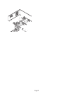
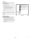
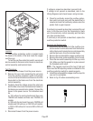
Triac Assembly Removal and Replacement
NOTE - each triac installation requires the use of an
approved silicone heat sink compound. Bunn-O-
Matic recommends the use of Dow Corning 340 com-
pound or equivalent. It can be purchased direct from
Bunn-O-Matic (part number M2522.0002).
P784
1. Place the tank heater switch on the electronic
control assembly in the “OFF” position.
2. Completely drain the tank.
3. Place a stryofoam or wood block between the
center of the tank and the rear of the brewer.
4. Disconnect triac wires, white/violet from terminal
block, blue from right tank heater, blue from
electronic control and tan from tank heater switch.
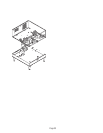
5. Carefully set the brewer on its back.
6. Remove the two 2" dia. hole plugs from the bottom
cover.
7. Remove the four #10-32 keps nut securing tank to
tank mounting bracket.
8. Remove the twelve #8-32 slotted head screws
securing the bottom cover.
9. Remove the bottom cover with the four feet, the
tank mounting brackets, triac/heat sink as an
assembly.
10. Remove triac/heat sink from right tank mounting
bracket and discard.
27040 032201
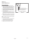
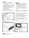
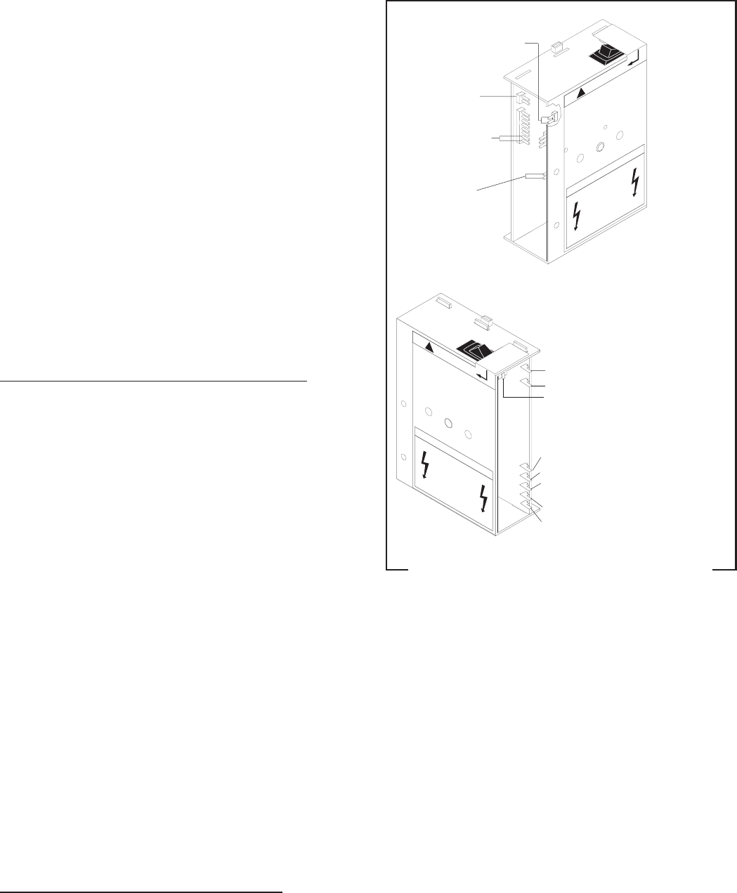
FIG. 12 ELECTRONIC CONTROL BOARD
TERMINALS
GRY to GRY to
InterLock Assy
WHI & WHI to
Temperature Sensor
PNK (Top) &
GRY (Bottom) to
Interlock Assy
PNK (Top) & GRY
(Bottom) from LED
#7 BLU from Triac Assy
#6 WHI/BRN to Tank Heater Switch
TAN from Triac Assy to Tank Heater
Switch
#5 PNK to Liquid Level Probe
#4 RED to Terminal Block (Red Insert)
#3 BLK to RED Lead from Liquid Level
Switch
#2 GRN to Ground
#1 WHI/BLU to Solenoid