


Page 32
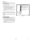
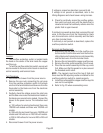
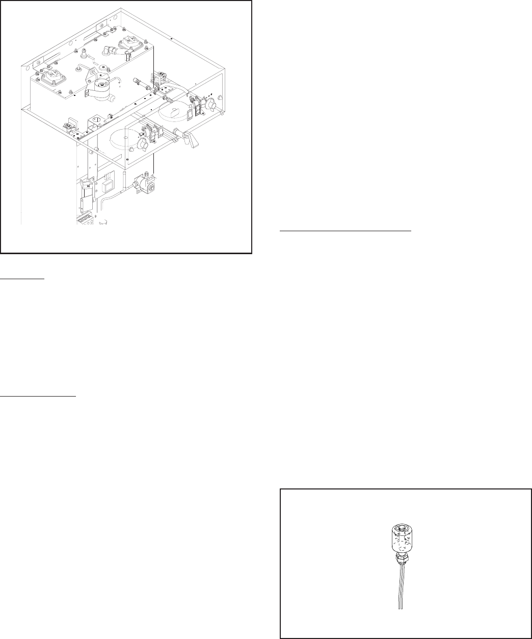
Location:
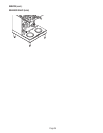
The overflow protection switch is located inside
the hood on the center of the tank inside the copper
overflow cup.
To test the overflow protection switch, access will
also be needed to the level control board or electronic
control assembly and terminal block.
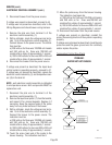
Test Procedure:
1. Disconnect the brewer from the power source.
2. Remove the wire nuts connecting the red wires
from the overflow protection switch to the black
wire from the terminal block and blue wire from the
thermostat or the black wire from the electronic
control assembly.
3. Carefully check the voltage across the violet wire
and the blue wire on electro/mechanical models or
the black wires on electronic models. Connect the
brewer to the power source. The indication must
be:
a.) 120 volts ac for electro/mechanical three wire
120/208 volt models and three wire 120/240 volt
models.
b.) 208 volts for electronic three wire 120/208 volt
models and 240 volts ac on 120/240 volt models.
c.) 200 to 240 volts ac for two wire 200 or 240 volt
models.
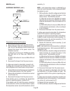
4. Disconnect brewer from the power source.
If voltage is present as described, proceed to #5.
If voltage is not present as described, refer to the
Wiring Diagrams
and check brewer wiring harness.
5. Check for continuity across the overflow protec-
tion switch red wires only until the plastic float is
raised and check that continuity returns when the
plastic float is again lowered.
If continuity is present as described, reconnect the red
wires to the blue wire from the thermostat or black
wire from electronic control assembly and the black
wire from terminal block.
If continuity is not present as described, replace the
overflow protection switch.
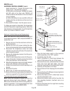
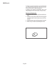
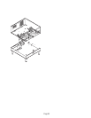
Removal and Replacement:
1. Disconnect the red leads from the overflow pro-
tection switch from the blue wire from the thermo-
stat or black wire from electronic control assembly
and the black wire from the terminal block.
2. Remove the nut beneath the copper overflow cup.
3. Remove the entire switch assembly from the cup.
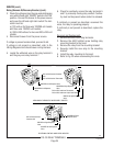
4. Place the new switch assembly into the cup, wires
first. Make sure that the gasket is in place around
the threaded switch stem.
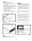
NOTE - The magnets must be at the top of float and
there must be NO adjusting washers installed for the
overflow protection switch to operate properly.
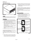
5. Install the nut beneath the copper overflow cup. Be
sure not to overtighten.
6. Refer to Fig. 23 when reconnecting wires.
P795
S
T
A
R
TON
/ WA
R
M
E
R
S
E
LE
C
TO
R
R
E
A
D
Y
R
E
A
D
Y
O
N
/ WARM
E
R
S
T
A
R
T
1
1
⁄2
g
al
1
ga
l
1
⁄
2
ga
l
S
E
LE
C
T
OR
1
1⁄
2
g
al
1
ga
l
1⁄
2
ga
l