


Page 34
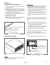
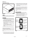
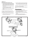
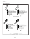
RED
BLK to BLK Lead on Contactor
Coil
BLK to BLK Lead on Thermostat
WHI/RED to Left Dispense Valve
WHI/BRN to Left Dispense
Valve
WHI/GRN to Right Dispense
Valve
BLU to BLU Lead from Thermostat
BLU to BLU Lead from Liquid Level Board
WHI/VIO to Right Dispense
Valve
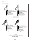
RIGHT
LEFT
GRY to BLK Lead from
Contactor Coil
WHI/VIO to Right Dispense
Valve
WHI/RED to Left Dispense
Valve
WHI/GRN to Right
Dispense Valve
ELECTRONIC CONTROL W/RECOVERY BOOSTER
MECHANICAL THERMOSTAT W/RECOVERY BOOSTER
B
A
A
7
7
5
5
B
B
5
7
A
P797
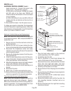
SERVICE (cont.)
Relay (Brewers W/Recovery Booster) (cont.)
3. Check the voltage across the gray and white/green
wire with left and right "ON/OFF" switch in the "ON"
position. Connect the brewer to the power source
and press the left and right start switch.The indi-
cation must be:
a.) 120 volts ac for three wire 120/208 volt models
and three wire 120/240 volt models.
b.) 200 to 240 volts ac for two wire 200 or 240 volt
models.
4. Disconnect brewer from the power source.
If voltage is present as described, proceed to #5.
If voltage is not present as described, refer to the
Wiring Diagrams
and check brewer wiring harness.
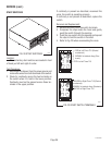
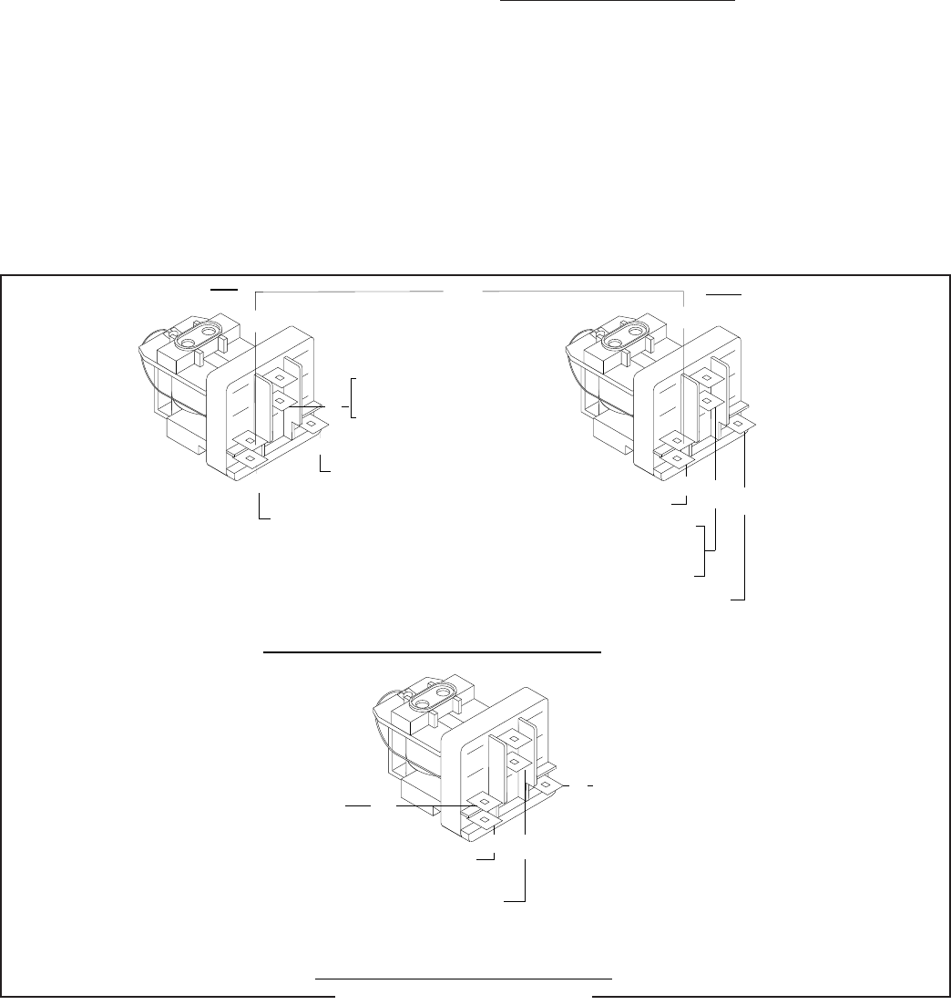
5. Locate the white/red wire on the relay terminal 5
and the gray wire relay terminal 7.
6. Check for continuity across the relay terminals 5
and 7 by manually closing relay contact. Continu-
ity must not be present when contact is released.
If continuity is present as described, reconnect the
wires, the relay is operating properly.
If continuity is not present as described, replace the
relay.
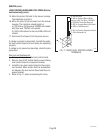
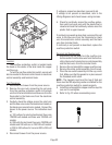
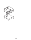
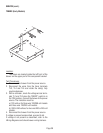
Removal and Replacement:
1. Remove all wires from relay terminals.
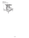
2. Remove the #8-32 slotted screw holding relay
mounting bracket to the hood.
3. Remove the relay from the mounting bracket.
4. Securely install the new relay to the mounting
bracket.
5. Install the relay mounting to the hood.
6. Refer to Fig. 25 when reconnecting the wires.
27040 032201
FIG. 25 RELAY TERMINALS