


Page 27
SERVICE (cont.)
LEVEL CONTROL BOARD AND LEVEL PROBE
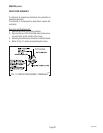
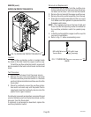
P832
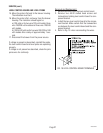
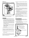
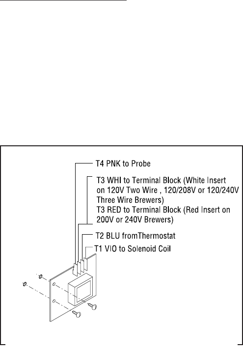
FIG. 19 LEVEL CONTROL BOARD TERMINALS
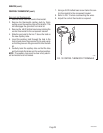
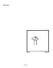
15. Move the probe's flat end to the brewer housing.
The indication must be 0.
16. Move the probe's flat end away from the brewer
housing. The indication should again be
a.)120 volts ac for two wire 120 volt models, three
wire 120/208 volt models and three wire 120/240
volt models.
b.) 200 to 240 volts ac for two wire 200, 230 or 240
volt models after a delay of approximately 1 sec-
ond.
17. Disconnect the brewer from the power source.
If voltage is present as described, reinstall the probe,
the level control board and level probe are operating
properly.
If voltage is not present as described, check the pink
probe wire for continuity.
28230 092200
Removal and Replacement:
1. Remove all wires from the level control board.
2. Remove two #8-32 slotted head screws and
lockwashers holding level control board to com-
ponent bracket.
3. Install the new level control board to the compo-
nent bracket. Make certain that the lockwashers
are between the level control board and the com-
ponent bracket.
4. Refer to Fig. 19 when reconnecting the wires.