


Page 28
SERVICE (cont.)
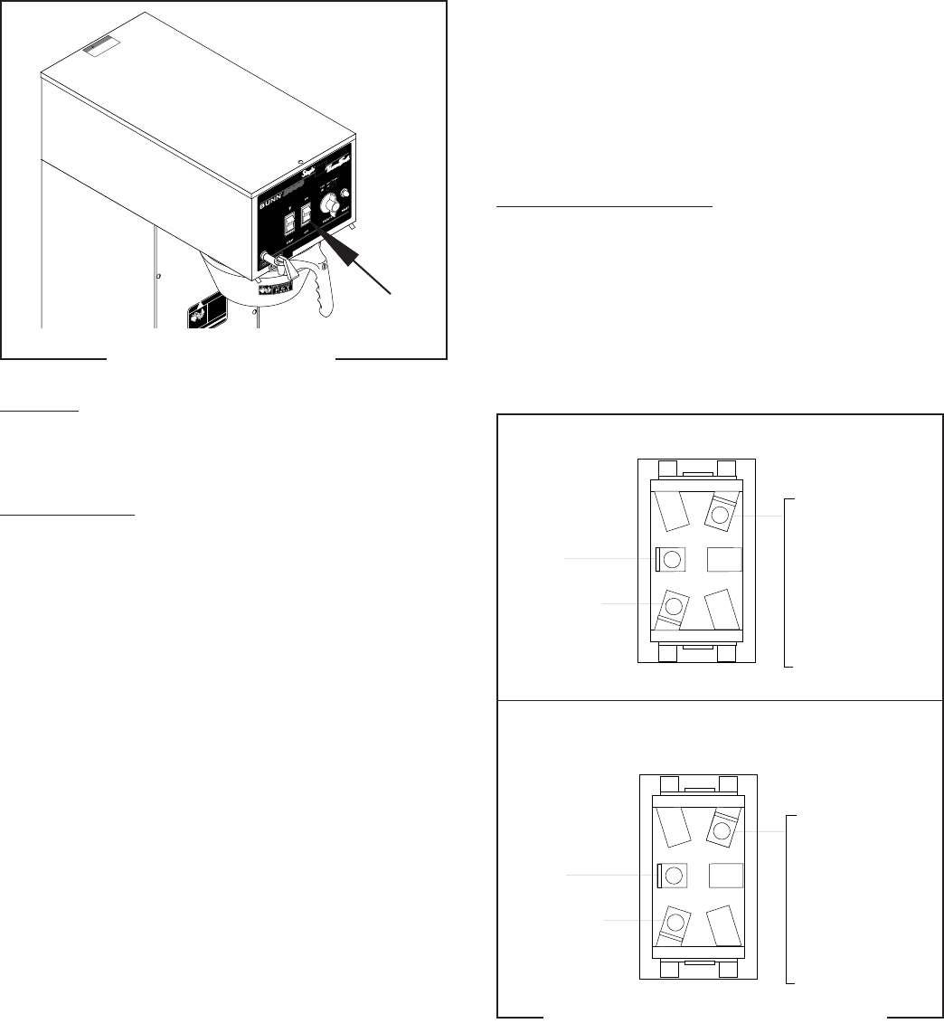
ON/OFF SWITCH
P1357
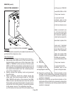
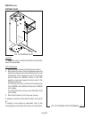
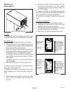
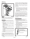
Location:
The ON/OFF switch is located on the front of the
hood in the center just to the right of the start switch.
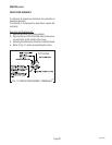
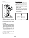
Test Procedure:
1. Disconnect the brewer from the power source.
2. Viewing the switch from the back remove the red
or white wire from the upper right terminal and the
black wire from the center terminal.
3. Check the voltage across the red or white wire and
the black wire with a voltmeter. Connect the brewer
to the power source. The indication must be:
a.) 120 volts ac for two wire 120 volt models, three
wire 120/208 volt models and three wire 120/240
volt models.
b.) 200 to 240 volts ac for two wire 200, 230 or
240 volt models.
4. Disconnect the brewer from the power source.
If voltage is present as described, reconnect the red or
white wire, and proceed to #5.
If voltage is not present as described, refer to the
Wiring Diagrams
and check the brewer wiring har-
ness.
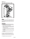
5. With the black wire removed, remove the white/
violet wire on the switch from the lower left
terminal.
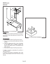
P1064
FIG. 20 ON/OFF SWITCH
6. Check for continuity across the center and lower
left terminal with switch in the "ON" position.
Continuity must not be present when switch is in
the "OFF" position.
If continuity is present as described, reconnect the
black wire to the center terminal and the white/violet
wire on the switch to the lower left terminal.
If continuity is not present as described, replace the
switch.
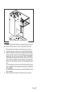
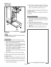
Removal and Installation:
1. Remove the wires from the switch terminals.
2. Compress the clips inside the hood and gently
push the switch through the opening.
3. Push the new switch into the opening and spread
the clips to hold switch in the hood.
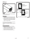
4. Refer to Fig. 21 when reconnecting the wires.
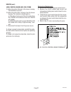
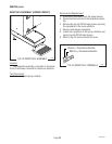
FIG. 21 ON/OFF SWITCH TERMINALS
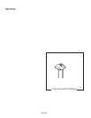
CAUTION
DISCARD DECANTER
IF:
. C
R
A
C
K
E
D
.
S
C
R
A
T
C
H
E
D
. B
O
IL
E
D
D
R
Y
.
H
E
A
T
E
D
W
H
E
N
E
M
P
T
Y
.
U
S
E
D
O
N
H
I
G
H
F
L
A
M
E
.
O
R
E
X
P
O
S
E
D
E
L
E
C
T
R
IC
E
L
E
M
E
N
T
S
OC
OMPLY RISKS INJURY
5
B
U
N
N
-O
-M
A
T
IC
C
O
R
P
O
R
A
T
IO
N
FU
N
NEL CONTENTS
ARE
HOT
!
!
C
A
U
T
I
O
N
H
O
T
W
A
T
E
R
D
I
S
C
O
N
N
E
C
T
F
R
O
M
P
O
W
E
R
S
O
U
R
C
E
B
E
F
O
R
E
R
E
M
O
V
A
L
O
F
A
N
Y
P
A
N
E
L
O
R
R
E
P
L
A
C
E
M
E
N
T
O
F
A
N
Y
C
O
M
P
O
N
E
N
T
!
WARNING
!
WHI/VIO to
Timer TL1
BLK to Terminal
Block (Black
Insert)
WHI to Terminal
Block ( White Insert
on 120V, 120/208V
or 120/240V Models)
RED to Terminal
Block (Red Insert
on 200V - 240V
Models)
WHI/VIO to
Timer TL1
BLK to Start
Switch and Black
to Terminal
Block (Black
Insert)
WHI to Terminal
Block ( White Insert
on 120V, 120/208V
or 120/240V Models)
RED to Terminal
Block (Red Insert
on 200V - 240V
Models)
WITH RELAY (Prior to S.N. SNG0014000)
WITHOUT RELAY(After S.N. SNG0014000)
28230 092200