


Page 31
SERVICE (cont.)
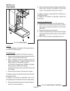
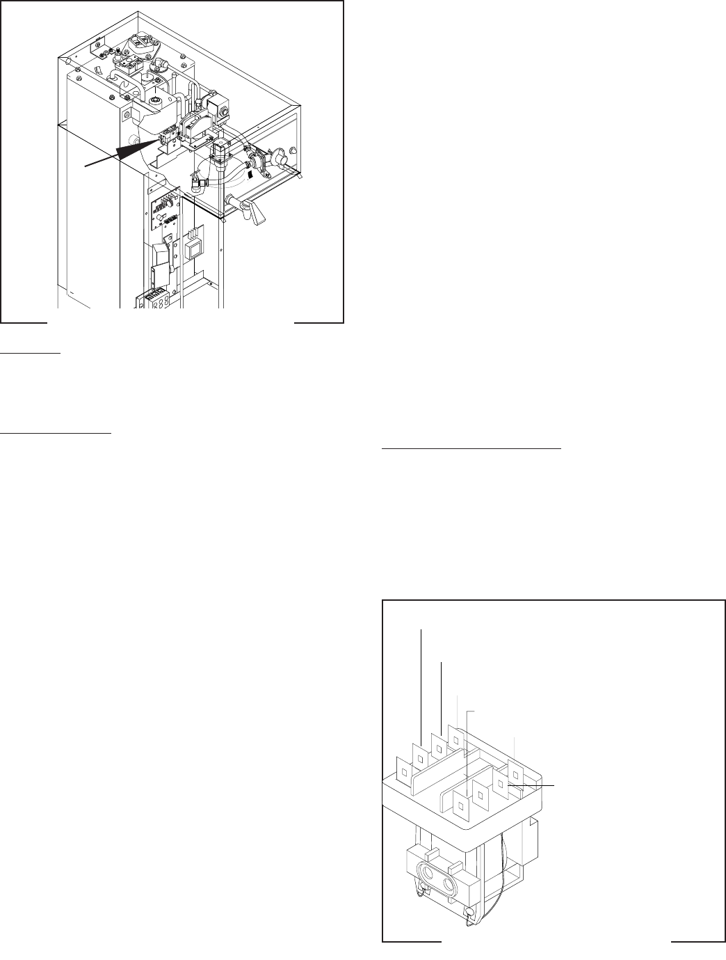
RELAY (SERVER POWER)(Prior to S.N. SNG0014000)
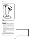
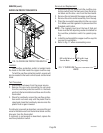
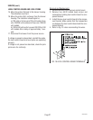
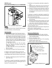
FIG. 26 SERVER POWER RELAY
Location:
The server power relay is located inside the hood,
left of the contactor in front of the tank.
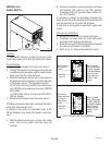
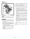
Test Procedures:
1. Disconnect the brewer from the power source.
2. Disconnect the white or red wire from terminal "B"
and the green wire from the terminal "A" of server
power relay coil. Check the voltage across the
white or red wire and the green wire. Connect the
brewer to the source. Place the ON/OFF switch in
the "ON" position, press and hold the start switch.
The indication must be:
a.) 120 volts ac for two wire 120 volt models,
three wire 102/208 volt models and three wire
120/240 volt models.
b.) 200 to 240 volts ac for two wire 200, 230 or
240 volt models.
3. Disconnect the brewer from the power source.
If voltage is present as described, proceed to #4.
If voltage is not present as described, refer to the
wiring diagram and check the brewer wiring harness.
4. Check for continuity across the "A" and "B" termi-
nals of the relay.
If continuity is present as described, reconnect the
white or red wire to terminal "B" and the green wire to
terminal "A" and proceed to #5.
22978.0000
TL5
TL4
TL3
TL2
TL1
J2
J1
S
E
T
L
O
C
K
LOCK
SET
1 2 3 4 5 6
P2230
If continuity is not present as described, replace the
relay.
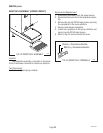
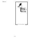
5. Disconnect the white/yellow from terminal 6 and
white/orange wire from terminal 9 on the relay.
6. Check for continuity across terminals 6 and 9 of
the relay by manually closing the relay contacts.
Continuity must not be present when the contacts
are released.
If continuity is present as described, reconnect the
white/yellow wire to terminal 6 and the white/orange
wire to terminal 9 of the relay.
7. Disconnect the black wires from terminals 1 and 7
from the relay.
8. Check for continuity across terminals 1 and 7 until
the contacts are manually opened and that conti-
nuity returns when the contacts are released.
If continuity was present as described, reconnect the
wires to terminals 1 and 7.
If continuity was present as described in steps #6 and
#8 the relay is operating properly.
If continuity is not present as described, replace the
relay.
Removal and Replacement:
1. Remove all the wires from the relay terminals.
2. Remove the #6-32 screw securing the relay to the
relay mounting bracket.
3. Remove and discard relay.
4. Securely install the new relay to the mounting
bracket using a #6-32 screw.
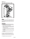
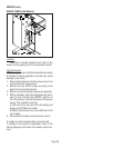
5. Refer to Fig. 27 when reconnecting the wires.
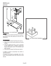
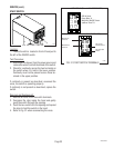
FIG. 27 SERVER POWER RELAY
P1385
B - WHI or RED to Terminal Block
A - GRN to Start Switch
1 - BLK to Transformer (1)
7 BLK to Terminal Block
9 - WHI/ORN to Brew Timer TL3
6 - WHI/YEL to Brew Timer TL5
28230 092200