


Page 16
SERVICE (cont.)
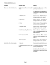
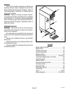
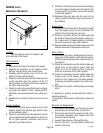
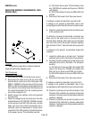
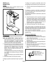
BREW SELECTOR SWITCH
Location:
The brew selector switch is located in the
front right side of the hood.
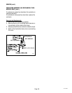
Test Procedure:
Timer:
1. Disconnect the brewer from the power supply.
2. Separate the connector on the selector switch
harness from the brew timer circuit board.
3. Carefully slide the plastic cover off of the con-
nector from the switch harness.
4. Check for continuity across the pink and tan wires
on the connector when the switch is in the 1/2
gallon position. Continuity must not be present in
any other switch position.
5. Check for continuity across the pink wire and gray
wire when the switch is in the 1 gallon position.
Continuity must not be present in any other posi-
tion.
6. Reattach the connector to the brew timer circuit
board.
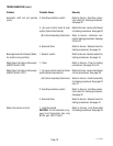
Grinder Interface:
7. Disconnect the pink, gray and tan wires on the
selector switch from the pink, gray and tan wires
on the interface socket.
8. Check for continuity across the pink wire and tan
wire on the selector switch when the switch is in
the 1/2 gallon position. Continuity must not be
present in any other position.
9. Check for continuity across the pink wire and gray
wire on the selector switch when the switch in the
1 gallon position. Continuity must not be present
in any other position.
10. Reconnect the pink, gray and tan wires on the
selector switch to the pink, gray and tan wires on
the interface.
Bypass Valve:
11. Disconnect the white/violet on the selector switch
from the bypass valve coil and disconnect the
white/red from the dispense valve coil.
12. Check for continuity across the white/violet and
the white red wires when the selector switch is in
the 1 gallon and 1-3/4 gallon position. Continuity
must not be present in any other position.
13. Reconnect the white/violet to the bypass valve coil
and the white/red to the dispense valve coil.
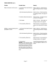
Server Sensor:
14. Disconnect the yellow, white/orange and the or-
ange wires of the selector switch from the yellow,
white/orange and orange wires of the brewer wir-
ing harness.
15. Check for continuity across the white/orange and
yellow wires on the selector switch when the
switch is in the 1/2 gallon position. Continuity
must not be present in any other position.
16. Check for continuity across the white/orange and
orange wires on the selector switch when the
switch is in the 1 gallon and 1-3/4 gallon position.
Continuity must not be present in any other posi-
tion.
17. Reconnect the yellow, white/orange and orange
wires.
If continuity is present as described the switch is
operating properly.
If continuity is not present as described, replace the
switch.
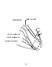
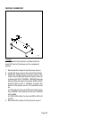
Removal and Replacement:
1. Disconnect the connector on the selector switch
harness from the brewer timer circuit board.
2. Disconnect wires from the selector switch, inter-
face socket, dispense valve, bypass valve and
proximity sensor harness.
3. Loosen the set screw on the switch knob.
4. Remove the 9/16" nut and washer holding the
switch to the hood.
P1014
CAUTION
D
IS
C
A
R
D
D
E
C
A
N
TE
R
I
F:
. C
R
A
C
K
E
D
. S
C
R
A
T
C
H
E
D
. B
O
I
L
E
D
D
R
Y
.
H
E
A
T
E
D
W
H
E
N
E
M
P
T
Y
.
U
S
E
D
O
N
H
I
G
H
F
LA
M
E
.
O
R
E
X
P
O
S
E
D
E
L
E
C
T
R
IC
E
L
E
M
E
N
T
S
FA
ILU
RE
TO
C
O
M
PL
Y
R
IS
KS
INJ
U
RY
P
N
:
65
8
1
9
8
5
B
U
N
N
-
O
-
M
A
T
I
C
C
O
R
P
O
R
A
T
I
O
N
FU
N
N
EL
C
O
NT
E
NT
S
A
R
E
H
OT
!
O
P
E
R
A
T
IN
G
P
R
O
C
E
D
U
R
E
S
1
.
C
h
e
c
k
S
e
r
v
e
r
s
iz
e
i
f
B
r
e
w
e
r
re
f
u
s
e
s
t
o
b
re
w
.
2
.
M
c
D
o
n
a
ld
's
B
r
e
w
T
e
m
p
e
r
a
t
u
r
e
: 2
0
0
°
F
±
5
°
(3
-1
8
-9
6
)
!
CA
UTI
O
N
H
OT WATER
DISCONNECT FROM POWER SOURCE
B
EFORE REMOVAL OF ANY PANEL
OR
RE
PLACEMENT OF ANY COMPONENT!
W
A
R
N
IN
G
!
27118 100400