


Page 32
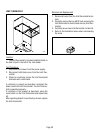
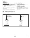
Removal and Replacement:
1. Disconnect the red leads from the overflow pro-
tection switch from the black wire from the termi-
nal block and the blue wire from the thermostat or
black wire from electronic control assembly.
2. Remove the nut beneath the copper overflow cup.
3. Remove the entire switch assembly from the cup.
4. Place the new switch assembly into the cup, wires
first. Make sure that a gasket is in place around the
threaded switch stem.
NOTE - The magnets must be at the top of float and
there must be NO adjusting washers installed for
the overflow protection switch to operate prop-
erly.
5. Install the nut beneath the copper overflow cup. Be
sure not to overtighten.
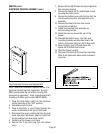
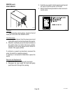
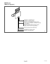
6. Refer to the illustration below when reconnecting
wires.
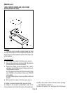
OVERFLOW PROTECTION SWITCH
SERVICE (cont.)
P999
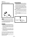
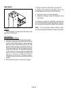
Location:
The overflow protection switch is located inside
the hood on the tank inside the copper overflow cup.
To test the overflow protection switch, access will
also be needed to the level control board or electronic
control assembly and terminal block.
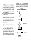
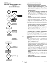
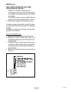
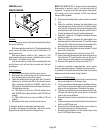
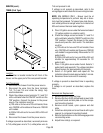
Test Procedure:
1. Disconnect the brewer from the power source.
2. Remove the wire nuts connecting the red wires
from the overflow protection switch to the black
wire from the terminal block and blue wire from the
thermostat or the black wire from the electronic
control assembly.
3. Check for continuity across the safety overflow
switch red wires only until the plastic float is raised
and check that continuity returns when the plastic
float is again lowered.
If continuity is present as described, reconnect the red
wires to the black wire from the terminal block and the
blue wire from the thermostat or black wire from
electronic control assembly.
If continuity is not present as described, replace the
safety overflow switch.
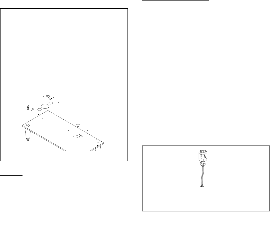
RED to BLU Lead
from Thermostat or to
BLK Wire from Electronic
Control Assy
RED to BLK Wire from
Terminal Block
P1065