


Page 26
SERVICE (cont.)
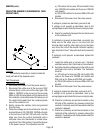
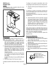
ELECTRONIC CONTROL ASSEMBLY (cont.)
If voltage was present as described, the temperature
control of the system is operating properly.
If voltage was not present as described, contact Bunn-
O-Matic to order an electronic control assembly (1),
temperature sensor (8), and triac assembly (15) for
revaluation and proceed to #9.
9. Replace the electronic control assembly (1) and
temperature sensor (8).
NOTE - each electronic control assembly is calibrated
to a temperature sensor. Both components MUST
be replaced as a set.
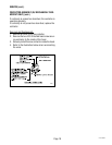
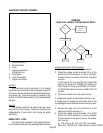
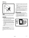
10. Check the voltage across the tank heater terminals
(5) with a voltmeter. Connect the brewer to the
power source. The indication must be:
a.) 120 volts ac for two wire 120 volt models, 208
volts ac for three wire 120/208 volt models and
240 volts ac for three wire 120/240 volt models
while the red indicator on the circuit board is on or
blinking.
b.) 200 to 240 volts ac for two wire 200 or 240 volt
models while the red indicator on the circuit board
is on or blinking.
11. Disconnect the brewer from the power source.
If voltage was present as described, return the new
triac assembly (15) to Bunn-O-Matic for credit. The
temperature control of the system is operating prop-
erly.
If voltage was not present as described, reinstall your
existing electronic control assembly (1) and tempera-
ture sensor (8), and proceed to #12.
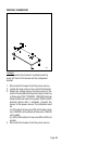
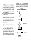
12. Replace the triac assembly (15).
13. Check the voltage across the tank heater terminals
(5) with a voltmeter. Connect the brewer to the
power source. The indication must be:
a.) 120 volts ac for two wire 120 volt models, 208
volts ac for three wire 120/208 volt models and
240 volts ac three wire 120/240 volt models while
the red indicator on the circuit board is on or
blinking.
b.)200 to 240 volts ac for two wire 200 or 240 volt
models while the red indicator on the circuit is on
or blinking.
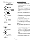
14. Disconnect the brewer from the power source.
If voltage was present as described, the temperature
control of the system is operating properly. Return the
new electronic control assembly (1) and temperature
sensor (8) to Bunn-O-Matic for credit.
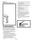
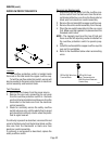
Electronic Controls Removal and Replacement
NOTE - each electronic control assembly is calibrated
to a temperature sensor. Both components MUST
be replaced as a set.
1. Remove all wires from the electronic control as-
sembly terminals.
2. Remove the two 8-32 screws holding the elec-
tronic control assembly to the component bracket.
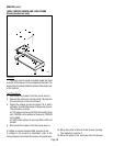
3. Disconnect the temperature sensor and ready
indicator wires from the left side of the electronic
control assembly board.
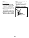
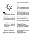
4. Remove the temperature sensor from the grom-
met in the tank lid.
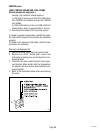
5. Install the new temperature sensor into the grom-
met on the tank lid. Route the wires to the location
of the new electronic control assembly.
6. Attach the temperature sensor and ready indicator
wires to the electronic control assembly.
7. Fasten the new electronic control assembly to its
bracket.
8. Reconnect the wires.
9. Refer to the illustrationon next page when recon-
necting the wires.
10. Review the initial set-up procedures and adjust the
control as required for the desired temperature.
27118 100400