


Page 25
YES
YES
YES
YES
NO
NO
NO
NO
YES
NO
NO
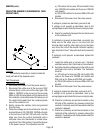
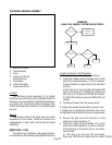
MEASURE VOLTAGE
AT TANK HEATER (5)
VOLTAGE PRESENT
REPLACE TANK
HEATER (5)
LIMIT THERMOSTAT (6)
OK
?
REPLACE LIMIT
THERMOSTAT (6)
REPLACE CONTROL
ASSEMBLY (1)
MEASURE VOLTAGE
AT TANK HEATER (5)
VOLTAGE PRESENT
REPLACE TRIAC (15)
CHECK FOR SPLIT
TANK HEATER (5)
REINSTALL ORIGINAL
CONTROL ASSEMBLY (1)
RECHECK WATER
TEMPERATURE
LED ON CONSTANTLY
TURN TEMPERATURE
ADJUSTING SCREW (14)
CLOCKWISE CONTINUOUSLY
LED ON
?
REPLACE CONTROL
ASSEMBLY (1)
ADJUST FOR CORRECT
WATER TEMPERARURE
SERVICE (cont.)
ELECTRONIC CONTROL ASSEMBLY (cont.)
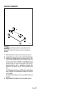
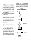
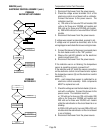
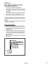
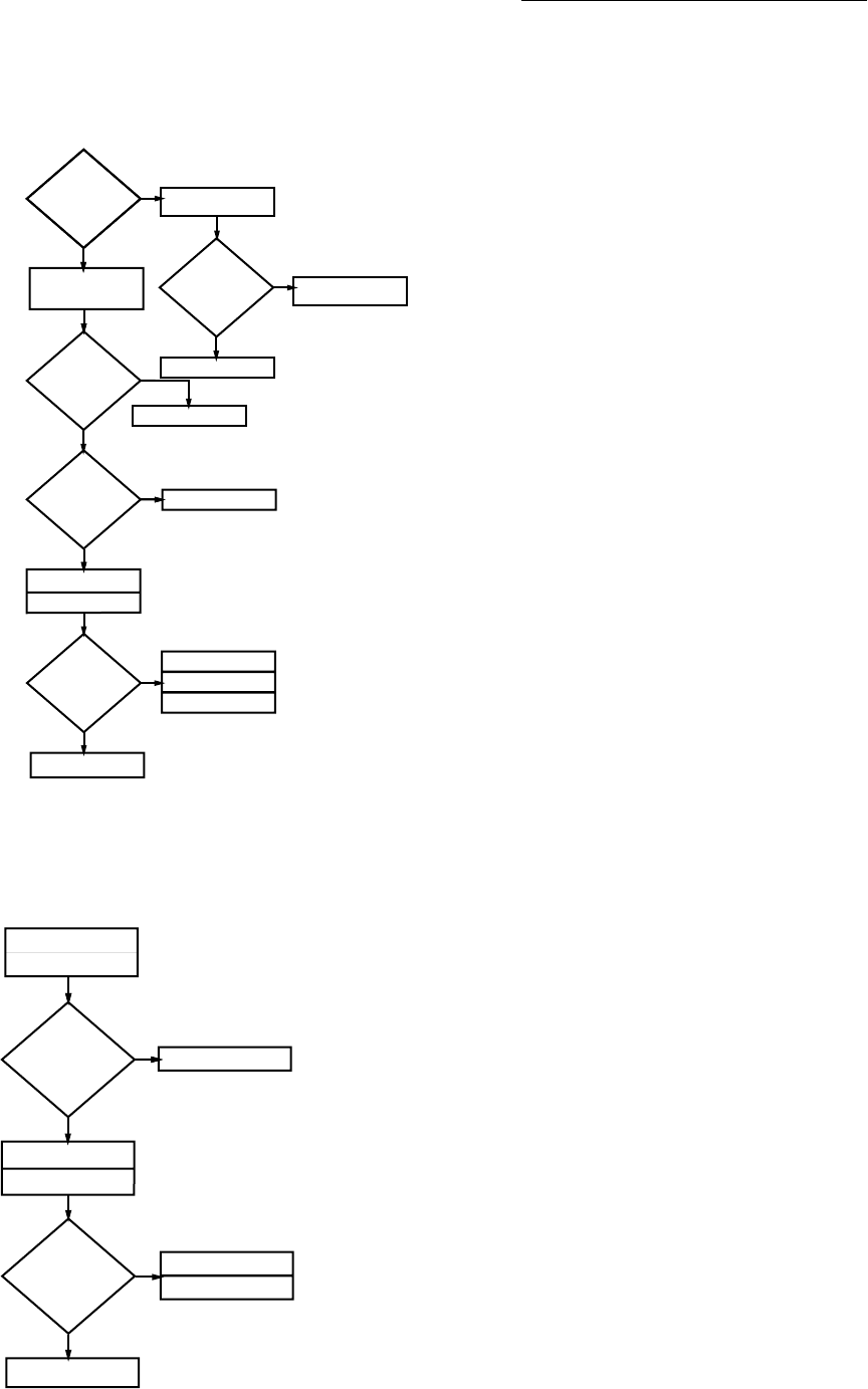
PROBLEM:
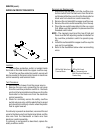
WATER BOILS
PROBLEM
WATER NOT HOT ENOUGH
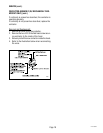
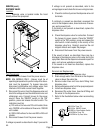
Temperature Control Test Procedure
1. Disconnect the brewer from the power source.
2. Check the voltage across terminals 3 & 4 of the
electronic control circuit board with a voltmeter.
Connect the brewer to the power source. The
indication must be:
a.) 120 volts ac for two wire 120 volt models, 208
volts ac for three wire 120/208 volt models and
240 volts ac for three wire 120/240 volt models.
b.) 200 to 240 volts ac for two wire 200 or 240 volt
models.
3. Disconnect the brewer from the power source.
If voltage was present as described, proceed to #4.
If voltage was not present as described, refer to the
wiring diagrams and check the brewer wiring harness.
4. Connect the brewer to the power source and place
the tank heater switch in the “ON” position.
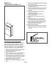
5. Observe the red LED indicator on the electronic
control circuit board (13).
6. Disconnect the brewer from the power source.
If the indicator was on or blinking, the temperature
sensor is operating properly, proceed to #7.
If the indicator was off, check the sensor connection
on the electronic control circuit board and/or replace
the temperature sensor (8) and the electronic control
assembly (1).
NOTE - each temperature sensor is calibrated to an
electronic control assembly. Both components
MUST be replaced as a set.
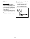
7. Check the voltage across the tank heater (5) termi-
nals with a voltmeter. Connect the brewer to the
power source. The indication must be:
a.) 120 volts ac for two wire 120 volt models, 208
volts ac for three wire 120/208 volt models and
240 volts ac for three wire 120/240 volt models
while the red indicator on the circuit board is on or
blinking.
b.)200 to 240 volts ac for two wire 200 or 240 volt
models while the red indicator on the circuit board
is on or blinking.
8. Disconnect the brewer from the power source.
P844
YES
NO
NO
NO
NO
REPLACE CONTROL
ASSEMBLY (1)
REPLACE TRIAC (15)
CHECK FOR SPLIT
TANK HEATER (5)
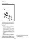
DRAIN CUP (4)
RETRY
LED (11)(13) ON
WHILE BOILING
DISCONNECT BLUE WIRE
FROM CONTROL BOARD PIN #7
RETRY
STILL BOILING
?
REPLACE CONTROL
ASSEMBLY (1)
P845
27118 100400