


Page 22
SERVICE (cont.)
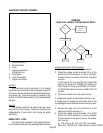
Test Procedures:
1. Disconnect the brewer from the power source.
NOTE: ECA MODELS ONLY - Brewer must be at
operating temperature to perform step #2 or brew-
lock must be bypassed. To bypass brew-lock
disconnect white/yellow and orange wires from
interlock of ECA and connect leads together.
2. Disconnect the wires from the dispense valve and
check the voltage across the white/violet wire and
white/green wire. Connect brewer to the power
source. Place the "ON/OFF" switch in the "ON"
position, press and release the start switch. The
indication must be:
a.) 120 volts ac for two wire 120 volt models, three
wire 120/208 volt models and three wire 120/240
volt models.
b.) 200 to 240 volts ac for two wire 200 or 240 volt
models.
3. Disconnect brewer from the power source.
If voltage is present as described in step 2 proceed to
#4.
If voltage is not present as described, refer to the
wiring diagrams and check the brewer wiring harness.
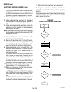
4. Check for continuity across the dispense valve coil
terminals.
If continuity is present as described, reconnect the
wires to the dispense valve, brew-lock wires if neces-
sary and proceed to #5.
If continuity is not present as described, replace the
dispense valve.
5. Check the dispense valve for coil action. Connect
the brewer to power source. Place the "ON/OFF"
switch in the "ON" position, press and release the
start switch. Listen carefully in the vicinity of the
dispense valve for a "clicking" sound as the coil
magnet attracts and repels the plunger.
6. Disconnect the brewer from the power source.
If the sound is heard as described, there may be a
blockage in the dispense valve or the water line to the
sprayhead. Remove the dispense valve and inspect for
wear, and remove waterborne particles.
If the sound is not heard as described, replace the
dispense valve.
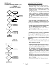
Removal and Replacement:
1. Disconnect wires from dispense valve.
2. Drain enough water from the tank so the dispense
valve is above the water line.
3. Remove water lines and hose barb fitting from
dispense valve.
4. Remove dispense valve from the sprayhead panel.
5. Install new dispense valve .
6. Reconnect the water lines, hose barb fitting and
the wires to the dispense valve.
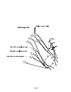
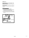
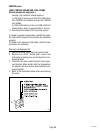
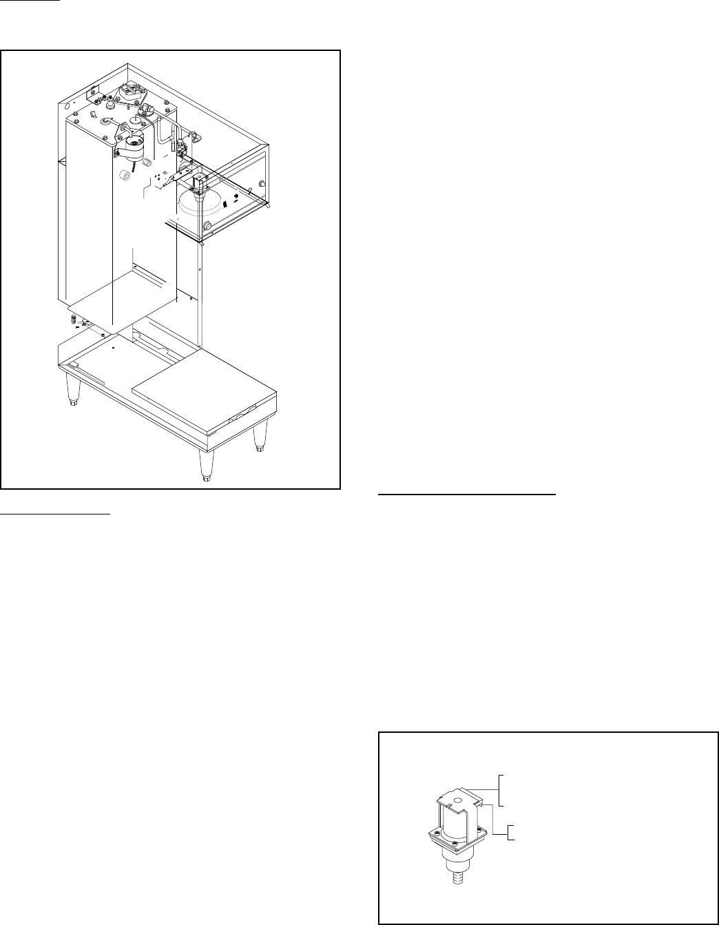
7. Refer to the illustration below when reconnecting
wires.
WHI/VIO to Timer TL1
WHI/VIO to ON/OFF Switch
WHI/RED to Brew Selector Switch
WHI/GRN to Timer TL4
WHI/GRN to By-Pass Valve
P829
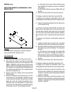
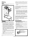
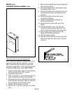
DISPENSE VALVE
Location:
Dispense valve is located inside the hood
directly above the sprayhead.
P999
22978.0000