


Frame Relay Status and Configuration
5-4 Configuring Frame Relay Ports
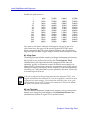
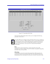
Possible line speed entries are:
75 64000 512000 1008000 1472000
150 72000 560000 1024000 1512000
300 112000 576000 1064000 1536000
600 128000 616000 1088000 1568000
1200 168000 640000 1120000 1600000
2400 192000 672000 1152000 1624000
4800 224000 704000 1176000 1664000
9600 256000 728000 1216000 1668000
14400 280000 768000 1232000 1728000
19200 320000 784000 1280000 1792000
24000 336000 832000 1288000 1856000
28800 384000 840000 1344000 1920000
38400 392000 896000 1400000 1984000
48000 448000 952000 1408000 2048000
56000 504000 960000 1456000
If you enter a value that is within the valid range but not equal to one of the
values listed above, the speed will be rounded up. If an RS-232 DCE port is
directly connected to the DTE via the standard Cabletron cable, the maximum
supported speed is 64000. If longer cabling is used, the maximum speed is 19200.
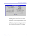
N1 Polling Count
The Polling Count speciÞes the number of polling cycles that must pass between
requests for full status reports, which include the status of all PVCs conÞgured on
the physical link. At an interval speciÞed by the T1 Link Integrity Timer
(described below), the logical data terminal equipment (DTE, or user-side
equipment, typically a workstation or router) will send a status enquiry to its
attached DCE (or network-side equipment), requesting the status of the network
link. Each exchange of one enquiry and one response (or status message) deÞnes
one polling cycle. After the number of cycles speciÞed by this value, a request for
a full status report will be sent.
N2 Error Threshold
The error threshold deÞnes the number of link reliability and/or protocol errors
that can occur during the period deÞned by the N3 Monitored Events Count
(described below) before the logical DCE is declared inactive.
NOTE
If this port is conÞgured as the logical data communications equipment (DCE), status
enquiries will be initiated at its attached DTE (or user-side equipment), and the local node
will respond with status messages. You can determine which link partner is the logical
DTE and which is the logical DCE (network-side equipment) by checking the Logical
DCE Þeld in this window (described below).