


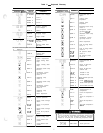
KEYBOARD
I
DISPLAY
ENTRY RESPONSE
q u
3
TEST
COMP
y$.
CAM
OFF
q
ENTR
CA1 ON
I
CAM
OFF
q
+
CA2 OFF
END TEST
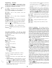
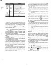
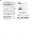
COMMENTS
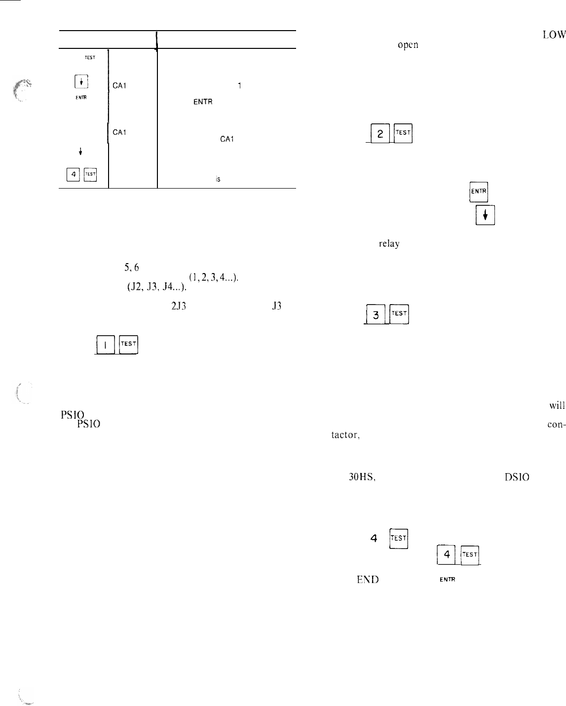
Factory field test of compressors
subfunction of test function
Circuit A, compressor
1
test
Pressing ENTR starts the test; when the
compressor should be running the
display shows CA1 on
If the test is allowed to time out, the
display will show
CA1
off
Pressing the down arrow key advances
the system to circuit A, compressor 2 test
If no other test
is
desired, exit quick test
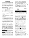
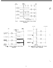
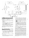
Refer to Fig.
5,6
and 7 for specific control wiring. Each
module in a panel is numbered
(
I,
2,3,4...).
Each terminal
strip is labeled (52, 53, J4...). The terminal strip on the
machine schematic combines the module and strip
numbers.
For example, 2JJ is terminal strip
53
on
module 2. The module numbers can be found on the com-
ponent arrangement label.
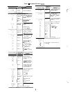
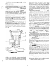
The
m
(;;;;I subfunction checks the thermistor and
switch inputs. The thermistor tests display the tempera-
ture that the thermistor is reading. If the display and the
actual temperature do not match, the thermistor and the
input channel can each be checked.
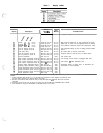
To check the thermistor, disconnect its leads from the
PSI0
terminal (the entire connector can be pulled from
the
PSI0
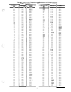
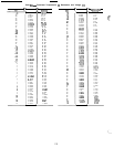
by pulling the connector to the left). Read the
resistance of the thermistor, then find the corresponding
temperature in Table 8.
This temperature should match the actual temperature
to which the thermistor is exposed.
The thermistor can be checked while connected to the
processor by measuring the voltage across its terminals
and finding the corresponding temperature in Table 8.
This method can only be used if it is certain that the
processor circuits are putting out the correct voltage. If
there is any doubt, the thermistor should be checked by
the resistance method.
The input channel can be tested by removing the
thermistor from the terminals and attaching a fixed
resistor with a value between 40,000 ohms and 400 ohms.
Refer to Table 8 and find the temperature that cor-
responds to that resistance; this temperature should
appear in the Quick Test display.
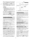
Loss of charge and oil pressure switch tests show LOW
if the switch is
open
and NRM or SAFE if the switch is
closed. The input channel can be tested by disconnecting
the switch and using a jumper to simulate a closed or open
circuit. (See Fig. 5.)
Note that the switch is read by the processor period-
ically, not continuously. When the switch position is
changed, it may take a few seconds before the display
changes.
The
[q
Fi
subfunction will energize the control
outputs except for the compressor control outputs. (See
Fig. 6.)
The liquid line solenoid and unloader solenoid tests
will energize the output when
ENTR
is pressed. It will
cl
remain energized until either the
0
J key is pressed or
10 minutes have elapsed. When the processor energizes
the output reiay it will display the word ON on the right
side of the display.
The EXV open and close tests drive the EXV fully open
or fully closed. See The EXV Checkout Procedure for
more information. The display will read either zero steps
open or 760 steps open.
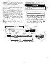
The
14
I;;;;]
subfunction energizes the compressor
control relays for 10 seconds and displays the compressor
status feedback.
The liquid line solenoid in the same circuit will ener-
gize for 10 seconds and the EXV will open 180 steps,
then close.
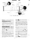
When control power reaches the compressor control
relay it also reaches the feedback terminal on terminal
strip 233 (see Fig. 7). When this occurs the display will
switch from OFF to UN. If the display changes but the
compressor does not start, check the control relay,
con-
tactor, compressor circuit breaker, interconnecting
wiring, and the compressor motor.
If the display does not change, check the discharge gas
thermostat, high-pressure switch, condenser fan overload
(on 30HS, if used), continuity across the DSIO terminals
and interconnecting wiring.
To protect the compressors from repeated cycling, a
delay of one minute is required before the same com-
pressor is retested.
The 4
q
a
TEST
subfunctions take the unit out of the
Quick Test mode. Press
14
H
and the display will
show EKD TEST; press
cl
ENS
and the display blinks and
then shows END TEST again.
15