


When the second or lag refrigeration circuit is started,
the circuit will go through a lo-second pumpout unless
the circuit has been operating in the 15 minutes prior to
this start.
Upon load reduction, the control system will unload
the unit in the reverse order of loading until the capacity
nearly matches the load. Each time the lead compressor is
cycled off, the liquid line solenoid valve and electronic
expansion valve will be closed for 10 seconds prior to
compressor shutdown to clear the cooler of liquid
refrigerant.
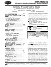
Unit Shutdown
-
To stop unit, move the RUN/
STANDBY switch to the STANDBY position. Any
refrigeration circuit that is operating at this time will
continue for 10 seconds to complete the pumpout cycle.
(Lag compressors stop immediately, lead compressors
run for 10 seconds.)
Complete Unit Stoppage can be caused by any of
the following conditions:
a.
b.
C.
d.
e.
f.
g.
h.
general power failure
blown fuse in control power feed disconnect
open control circuit fuse
RUN/STANDBY switch moved to STANDBY
freeze protection trip
low flow protection trip
open contacts in chilled water flow switch (optional)
open contacts in any auxiliary interlock. (Terminals
TBI-13 and TBJ-14, jumpered from factory, are in
series with the control switch. Opening the circuit
between these terminals places the unit in STANDBY
mode, just as moving the control switch to STANDBY
would. Code26 will appear as the operating mode
in the status function display. The unit cannot start
if these contacts are open, and if they open while unit
is running, it will pump down and stop.
Single Circuit Stoppage can be caused by the
following:
a. open contacts in
lead compressor discharge gas
thermostat
b. open contacts in loss of charge switch
c. open contacts in oil safety switch
d. open contacts in lead compressor high-pressure switch
Stoppage of one circuit by a safety device action does
not affect the other circuit. Besides stopping com-
pressor(s), all devices listed will also close liquid line
solenoid valve for that circuit.
Lag Compressor Stoppage can be caused by the
following:
a. open contacts in discharge gas thermostat
b. open contacts in high-pressure switch
If stoppage occurs more than once as a result of any
of the above safety devices, determine and correct the
cause before attempting another restart.
Restart Procedure, after cause for stoppage is
corrected.
GENERAL POWER FAILURE
~
Unit will restart
automatically when power is restored.
BLOWN FUSE IN POWER FEED DISCONNECT
~
Replace fuse. Restart is automatic.
LOW WATER TEMPERATURE CUTOUT Move
RUN/ STANDBY switch to STANDBY, then back to
RUN. Restart is automatic.
AUXILIARY INTERLOCK
~-
Automatic restart after
condition is corrected.
OPEN CONTROL CIRCUIT FUSE
“--
Replace fuse.
Unit will restart automatically.
FREEZE PROTECTION
-
Unit will automatically
restart when leaving water temperature is 6 degrees F
above the leaving water set point.
HIGH-PRESSURE SWITCH, LOSS OF CHARGE
SWITCH, COMPRESSOR DISCHARGE TEM-
PERATURE SWITCH AND OIL SAFETY SWITCH
-- Move the RUN;‘STANDBY switch to STANDBY,
then back to RUN. Unit will restart automatically.
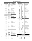
CONTROLS OPERATION
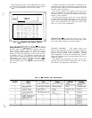
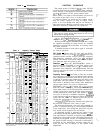
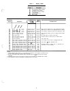
Accessing Functions and Subfunctions
-
Table 5. Refer also to Table 2, which shows the 5 func-
tions (identified by name) and the subfunctions(identified
by number). Table 6 shows the sequence of all the ele-
ments in a subfunction.
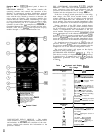
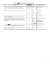
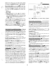
Display Functions
SUMMARY DISPLAY
~
Whenever the keyboard has
not been used for 10 minutes, the display will auto-
matically switch to an alternating summary display. This
display has 4 parts, shown below, which alternate in
continuous rotating sequence.
Display
Expansion
TUE
12:45
TODAY IS TUE, TIME IS
12:45
MODE 26
UNIT STANDBY
1 STAGES NUMBER OF STAGES IS 1
2 ALARMS
2 ALARMS DETECTED
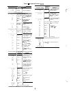
STATUS FUNCTION
~
The status function shows the
current status of alarm (diagnostic) codes. capacity
stages, operating modes,
chilled water set point. all
measured system temperatures, superheat values, pres-
sure switch positions and expansion valve positions.
These subfunctions are defined below. Refer to Table 6
for additional information.
[r-r-j
pq
(Alarms) Alarms are messages that one or
more faults have been detected. Each fault is assigned a
code number which is reported with the alarm. (See
Table 7 for code definitions.) The codes indicate failures
that cause the unit to shut down, terminate an option
(such as reset) or result in the use of a default value
as set point.
Up to 3 alarm codes can be stored at once. To view
them in sequence, press
m
m
to enter the alarm
displays and then press key to move to the individ-
ual alarm displays. Press
I
EXPN)
after a code has been
dis-
played and the meaning of code will scroll across the
screen.
When a diagnostic (alarm) code is stored in the display
and the machine automatically resets, the code will be
deleted. Codes for safeties which do not automatically
reset will not be deleted until the problem is corrected
and the machine is switched to STANDBY, then back
to RUN.
confinued on page IO
5