


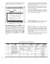
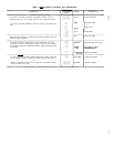
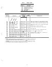
Each function has one or more subfunctions as shown At initial start-up the valve position is initialized to 0.
in Table 2. These functions are defined in greater detail After that, the microprocessor keeps accurate track of the
in t K Controls Operation section of this book.
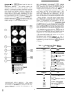
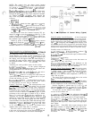
Fig. 2
-
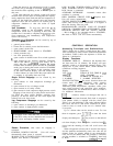
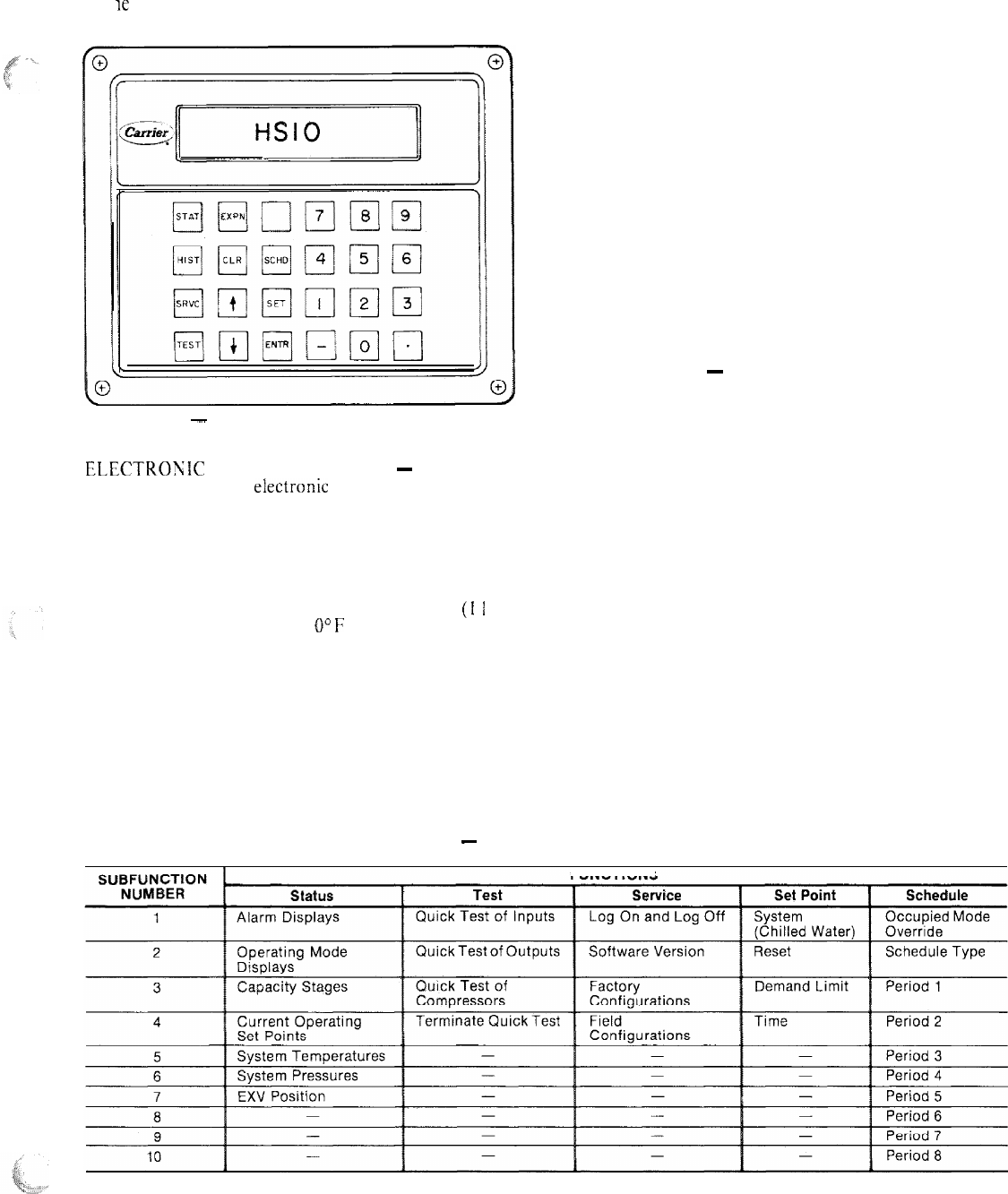
Keyboard and Display Module
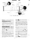
ELECTROWIC EXPANSION VALVE
~
The micro-
processor controls the electronic expansion valve through
the EXV driver module. Inside the expansion valve is a
linear actuator stepper motor. To control the stepper
motor’s position, the thermistor in the cooler and the
thermistor in the lead compressor in each circuit are used
to maintain a 20 F (1 I C) difference. Because the com-
pressor sensor is after the compressor motor, which adds
approximately 15 F (8.3 C) superheat, the 20 F
(1
I
C)
control temperature results in
U”F
to 5 F (2.8 C) super-
heat leaving the cooler. This improves the performance of
the cooler.
valve position in order to use this information as input for
the other control functions.
The control monitors the superheat and the rate of
change of superheat to control the position of the valve.
The valve stroke is very large; this results in very accurate
control of the superheat.
The electronic expansion valve is also used to limit the
maximum saturated suction temperature to 55 F (12.8 C)
to keep from overloading the compressor during high
cooler water temperatures. This allows the unit to start
with very warm water temperatures.
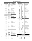
THERMISTORS
~
The electronic control uses 7 ther-
mistors to sense temperatures used to control the opera-
tion of the chiller. Sensors are listed in Table 3.
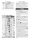
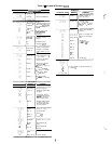
CAPACITY CONTROL
~
The control cycles com-
pressors and alternately loads and unloads cylinders to
give capacity control steps as shown in Table 4. The unit
controls leaving chilled water temperature. Entering
water temperature is used by the microprocessor in deter-
mining the optimum time to load and unload, but is not a
control set point.
The chilled water temperature set point can be auto-
matically reset by the return temperature reset or space
and outside air temperature reset features.
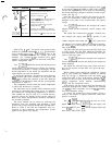
Table 2
-
Function and Subfunctions
FUNCTIONS