


-
Features
-
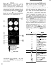
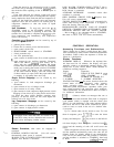
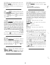
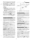
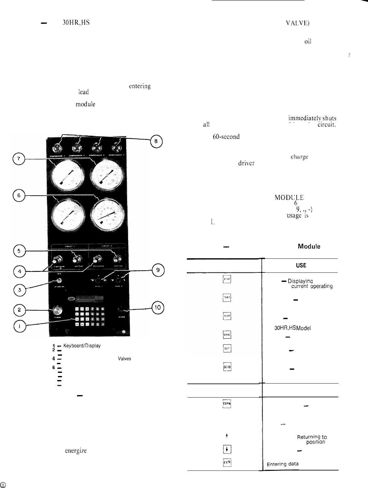
The 30HR,HS control panel is shown in
Fig. 1.
PROCESSOR MODULE
-
This module contains the
operating software and controls the operation of the
machine. It continuously monitors information received
from the various temperature thermistors and communi-
cates with the relay module to increase or decrease the
active stages of capacity. The processor module also
controls the EXV driver module, commanding it to open
or close each electronic expansion valve in order to main-
tain approximately 20 F of superheat entering the
cylinders of each of the
Iead
compressors, Information is
transmitted between the processor module and the relay
module, EXV driver moduIe and keybuard display
module through a 3-wire communications bus.
0
8
0
9
0
IO
EXV (ELECTRONIC EXPANSION VALVE) DRIVER
MODULE -- The EXV driver module operates the elec-
tronic expansion valves (based on commands from the
processor) and monitors the status of the
oi1
pressure
switches and the refrigerant Ioss of charge switches.
If the loss of charge switch opens due to a low refrig-
.:.
erant charge, the EXV driver module detects a zero
voltage condition in the loss of charge switch electrical
circuit and communicates this information to the pro-
cessor module. The processor module immediately shuts
down all compressors in the affected refrigeration circuit.
During operation, if the EXV driver module detects
zero voltage in the oil pressure switch electrical circuit
for 45 consecutive seconds (due to an open oil pressure
switch), it communicates this information to the pro-
cessor module. The processor module immediatelvshuts
down ali compressors in the affected refrigeration circuit.
At start-up, if the oil pressure switch has not closed by the
end of a 60-second time period the EXV driver module
senses this and the processor module immediately shuts
down all compressors in the affected refrigeration circuit.
If a shutdown occurs due to loss of
cftarse
or low oil
pressure, the EXV driver module communicates this to
the processor module and the processor module locks the
compressors off in the affected refrigeration circuit.
The proper fault code(s) will appear on the display
whenever a safety switch opens.
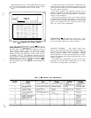
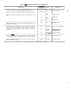
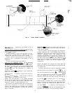
KEYBOARD AND DISPLAY MODKLE
-
(Fig. 2)
This device consists of a keyboard with
Cr
function keys,
5 operative keys, 12 numeric keys (0 to
9,
11
-)
and an
alphanumeric g-character LCD. Key
usage
ii;
explained
in Table
1.
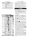
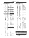
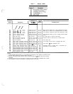
Table 1
-
Keyboard and Display Madule
-
Key Usage
FUNCTION
KEYS
I
-
Keyboard/Display Module
2
-
Control Power ON Light
3
-
RUN/STANDBY Switch
4
-
Discharge Pressure Gage
Valves
5
-
Suction Pressure Gage Valves
6
-
Suction Pressure Gages
7
-
Discharge Pressure Gages
8
-
Compressor ON Lights
9
-
Control Circuit Fuses
10
-
Alarm Light
0
SCHD
OPERATIVE
Fig. 1
-
Control Panel
KEYS
El
EXPN
q
CLR
LOW-VOLTAGE RELAY MODULE -- This module
closes contacts to energize compressors, solenoid valves
and unloaders. It also senses the condition of the com-
pressor safeties and transmits this information to the
processor module.
q
t
El
4
0
ENTR
LOSE
Status
-
Displayjng diagnostic
codes and current operating
information about the machine
Quick Test
-
Checking inputs
and outputs for proper
operation
History
-
This key appears on
the keyboard, but is not used on
the 30HR,HS
Modei
E machines
Service
-
Entering specific
unit configuration information
Set Point
-
Entering operating
set points and day/time
information
Schedule
-
Entering occupied/
unoccupied schedules for unit
operation
USE
Expand Display
-
Displaying a
non-abbreviated expansion of
the display
Clear
-
Clearing the screen of
all displays
Up Arrow
-
Rtjturnipg
to
previous display posItIon
Down Arrow
-
Advancing to
next display position
2