


Thermistors
-
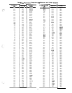
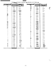
All thermistors are identical in their
temperature vs resistance performance. Resistance at
various temperatures are listed in Table 8.
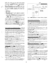
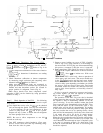
LOCATION -- General location of thermistor sensors
are shown in Fig. 9.
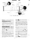
Cooler Leaving Water Sensor, TL, is located in the leav-
ing water nozzle. The probe is immersed directly in the
water. All thermistor connections are made through a
1,/4-in.
coupling (Fig. I I). Actual location is shown in
Fig. 4.
Cooler Entering Water Sensor, T2, is located in the cooler
shell in first baffle space, near to tube bundle. Actual
location is shown in Fig. 4.
Cooler Saturated Suction Temperature Sensors,
T5
and
T6, are located next to refrigerant inlet in cooler head.
Thermistors are immersed directly into refrigerant.
Typical location is shown in Fig. 4.
Compressor Suction Gas Temperature Sensors, T7 and
T8, are located in lead compressor in each circuit in a
suction passage between motor and cylinders, above
oil pump.
SENSOR REPLACEMENT
-
TI,
T2, T5, T6, T7,
T8
(Compressor and Cooler)
Sensors are installed directly in refrigerant or water
circuit. Relieve all refrigerant pressure or drain water
before removing.
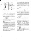
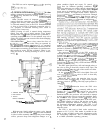
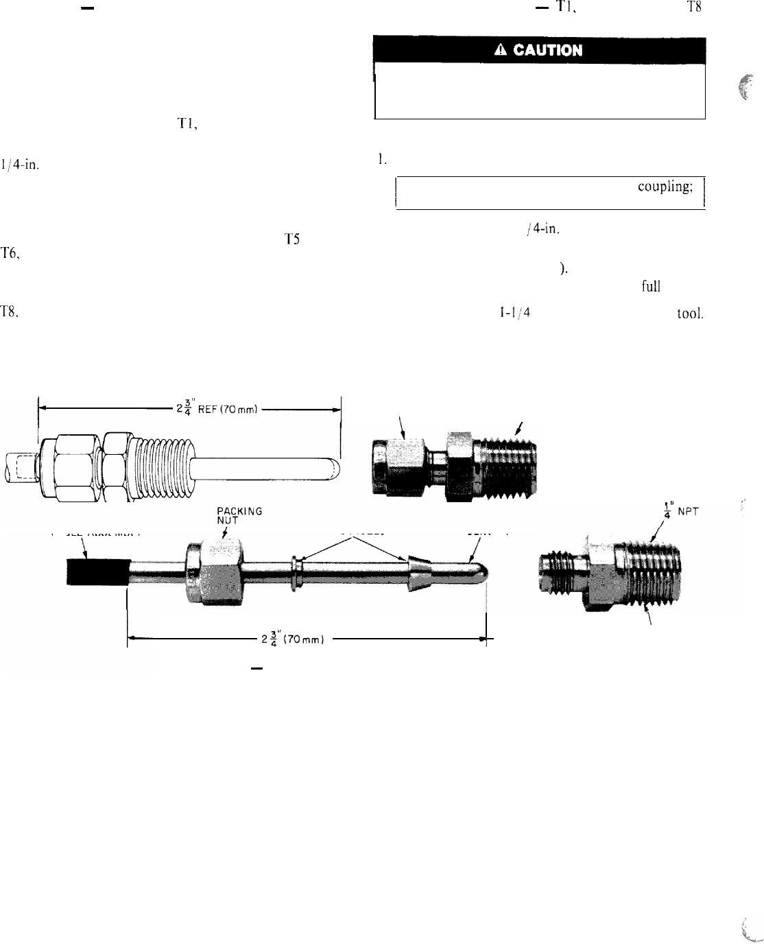
Proceed as follows (refer to Fig. I I):
I.
Remove and discard original sensor and coupling.
I
IMPORTANT: Do not disassemble new
couphng;
install as received.
I
2. Apply pipe sealant to I /4-in. NPT threads on replace-
ment coupling and install in place of original. Do not
use packing nut to tighten coupling; this would
damage ferrules (see Fig. I I
).
3. Insert new sensor in coupling body to its full depth.
Hand tighten packing nut to position ferrules, then
finish tightening I-1/4 turns with a suitable tool.
Ferrules are now attached to sensor, which can be
withdrawn from coupling for unit servicing.
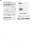
FERRULES
INSIDE
\
COUPLING
/ASSEMBLY
. II
,,
CABLE ASSEMBLY
FERRULES SENSOR
\
2$70mm)
COUPLING
‘f
BODY
Fig. 11
-
Thermistor (Compressor and Cooler)
22