


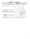
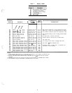
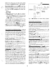
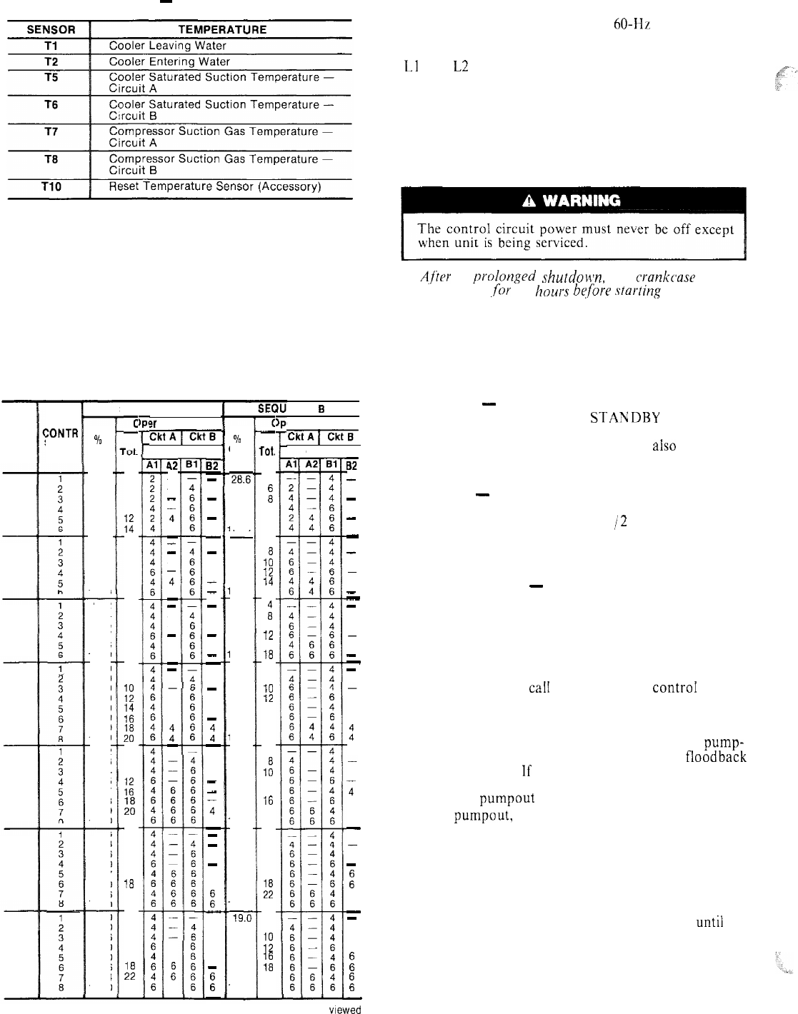
Table 3
-
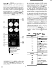
Thermistors
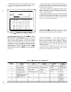
CONTROL SEQUENCE
The control power (115-l-60 for 60-Hz units; 230-l-50
for 50-Hz units) must be supplied directly from a separate
source through a code-approved fused disconnect to the
Ll
and L2 terminals of unit power teminal block.
NOTE: There is no switch or circuit breaker; only fuses. If
the control power feed is live, so is the circuit.
Crankcase heaters are wired into the control circuit.
They are always operative as long as control circuit
power is on even though unit may be off because of
safety device action. Heaters are wired so they are on only
when their respective compressors are cycled off.
A,f’tor
a prnlonged shutdoun, the
crankcause
heaters
should be on
,for
24
hours
hqfbre
starting
the unit.
When power is supplied to control circuit, unit is ready
for operation providing all safety devices are satisfied,
interlocks are closed and instructions on warning labels
have been followed.
If schedule function is used, refer to page 11 for details
on control operation.
Off Cycle
-
During unit off cycle when the RUN;
STANDBY switch is in the STANDBY position, the
crankcase heaters and the control system are energized.
The electronic expansion valves are
also
energized.
(NOTE: The control circuit power must be on at all times
even when the main unit power is off.)
Start-Up
-
When the RUN/STANDBY switch is
moved from the STANDBY to the RUN position and
there is a call for cooling, after l-l /2 to 3 minutes have
passed the first compressor will start unloaded, The first
circuit to start may be circuit A or B due to the automatic
lead/ lag feature.
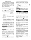
Capacity Control
-
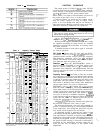
(See Table 4.) The rate at which
the compressors are turned on will depend on the leaving
water temperature difference from the set point, the rate
of change of leaving water temperature, the return water
temperature and the number of compressor stages on.
The control is primarily from leaving water temperature
and the other factors are used as compensation.
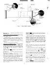
SEQUENCE -- On a
caiI
for cooling, the controI system
starts the initial compressor. The control will randomly
select either circuit A or B. The liquid line solenoid valve
remains closed for 10 seconds after the initial compressor
on that refrigeration circuit starts. This permits a pump-
out cycle at start-up to minimize refrigerant floodback
to the compressor. If the compressor in that refrigeration
circuit has run in the 15 minutes before the call for
cooling, the pumpout cycle is bypassed.
After pumpout, the liquid line solenoid valve opens and
the electronic expansion valve starts to open.
The electronic expansion valve will open gradually to
provide a controlled start-up to prevent liquid floodback
to the compressor. Also during this period, the oil pres-
sure switch will be bypassed for one minute.
As additional cooling is required, the control system
will ramp up through the capacity steps available until the
load requirement is satisfied. As capacity steps are added
compressors are brought on line, alternating between the
lead and lag refrigerant circuits. As explained previously,
the speed at which capacity is increased or decreased is
controlled by the temperature deviation from the set
point and the rate of change in the chilled water
temperature.
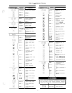
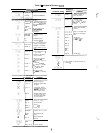
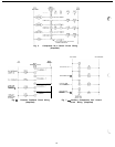
Table 4
-
Capacity Control Steps
SEQUENCE A
ENCE 3
er Cylinders
zlzqxi7
c
-
2
6
a
10
E
4
a
10
12
14
16
4
a
10
12
16
18
4
8
1:
::
::
4
a
10
:;
hi
22
4
a
10
12
16
1%
22
24
4
a
10
12
16
:;
24
c
-
rot.
4
:
10
12
14
4
1:
13
14
16
ii
10
12
16
18
4
a
10
12
14
16
18
20
4
1:
12
14
16
20
22
4
a
10
12
16
:;
24
4
8
iif
::
22
24
?r Cylinders
EiiqTm-
Compr
42
-
-
4
4
-
-
-
4
4
-
-
-
6
6
-
-
4
4
t
-
6
:
6
82
-
-
-
-
-
-
-
-
-
-
-
-
-
-
-
-
t
-
-
-
4
4
-
-
-
-
-
:
-
-
-
E
-
UNIT
30HR
30HS
:ONTR
STEPS
%
Cap.
14.3
42.9
57.2
71.2
85.7
100.0
25.0
50.0
62.5
75.0
87.5
100.0
%
Cap.
2&.6
42.9
57.2
71.2
85.7
00.0
25.0
50.0
62.5
75.0
87.5
00.0
22.2
44.4
55.5
66.7
88.8
‘00.0
20.0
40.0
50.0
60.0
70.0
80.0
90.0
100.0
18.2
36.3
45.4
54.5
63.6
72.7
90.9
t 00.0
16.6
33.3
41.6
50.0
66.7
75.0
91.6
100.0
19.0
38.0
47.6
57.0
69.0
78.6
90.4
100.0
Compr
B2
-
-
-
-
-
-
-
-
-
-
-
4
4
:
-
4
4
4
4
-
-
:
6
6
-
-
-
:
E
-
070
080
22.2
44.4
55.5
66.7
88.8
100.0
20.0
40.0
50.0
60.0
70.0
80.0
90.0
100.0
18.2
36.3
45.4
54.5
72.7
81.8
90.9
100.0
090
100
110
16.6
33.3
41.6
50.0
66.7
75.0
91.6
100.0
19.0
38.0
47.6
57.0
69.0
78.6
90.4
100.0
120,
160
140
NOTE: Circuits and
from front of unit.
compressors designated from ieft to right when viewed
4