


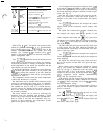
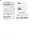
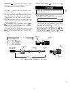
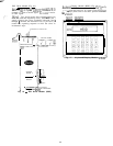


On the sensor bus terminal strips, terminal
1
of the
PSI0
module is connected to terminal 1 of each of the
other modules; terminals 2 and 3 are connected in the
same manner. (See Fig. 13.) If a terminal 2 wire is con-
nected to terminal 1, the system will not work.
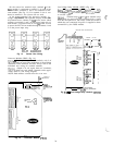
in the 30HK,HS units, the processor module, low-
voltage relay module, and keyboard! display module are
all powered from a common 21 vat power source which
connects to terminals 1 and 2 on the power input strip of
each module. A separate source of 12.5 vat power is used
to power the EXV driver module through terminals 1 and
2 on the power input strip.
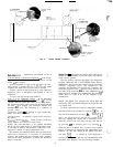
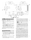
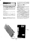
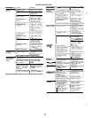
Low-Voltage Relay Module (DSIO) (Fig. 15.)
r#2j?2rt.s
--
Inputs on strip
.J3
arc discrcti: inputs (ON-
OFF).
When
24 vat are applied
itcross
the
2 tcrminah in
a channel it is
read
as an ON signal, Zero
vnl$s
is read
as an OFF signal.
0ulput.s
-
Terminal strips 54 and
.J5
are internal relays
whose coils are powered-up and powered-off by a signal
from the microprocessor. The relays switch the circuit to
which they are connected. No power is supplied to these
connections by the DSIO module.
SENSOR BUS CONNECTOR
/
INPUTS : 24 VAC
CHANNEL I
-
J3 PINS
I
2-
3- I
18 2
384
586
+
4-
+
788
2,4,6
88
ARE GROUND (C1
PSI0
DSIO
DSIO
HSIO
(RELAY)
(EXV DRIVER)
Fig. 13
-
Sensor Bus Wiring
COMMON
Is
CHANNEL
%fMoN
,%~MON
&MON
1:
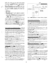
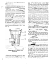
Processor Module (PSIO) (Fig. 14.)
Inputs
-
Each input channel has 3 terminals; only 2 of
the 3 terminals are used. The application of the machine
determines which terminals are used. Always refer to the
individual unit wiring for terminal numbers.
Outputs
~
Output is 24 vdc. Again, there are 3 terminals,
only 2 of which are used; which 2 depends on the appli-
cation. Refer to unit wiring diagram.
NOTE: Both address switches must be set at zero.
C%MoN
C&MON
K
COMMON
NO
C&MON
3
b
CHASS IS
GROUND
-
(REAR1
NETWORK
sfNNECTOR
‘(FORWARD)
SENSOR BUS
58”
NECToR
mm*
0
-r-awe4
ADDRESS ADJUSTMENT
I
(NOT SHOWNI ON UNDERSIDE.
Fig, 15
-
Low-Voltage Relay Module (DSIO)
ADDRESS
’
0
SW trcnEs
--l
0
PSI0
Fig. 14
-
Processor Module (PSiO)
24