


16
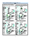
Note: IF either the Auger Motor, or Mixer Motor, or Solenoid Error Screen appear: The entire system is inoperable this means
that one of either the Auger Motor, or Mixer Motor, or Solenoid [Dispense Valve] is not functional while that Hopper Status in ON.
To continue operating the other Hoppers:
Go into Program Mode [by pressing simultaneously the Rinse and Stop keys],
Press RINSE to get the HOPPER STATUS screen, Press ▼or ▲key to set the non-functional HOPPER STATUS to OFF;
Wait at least 10 sec., then Exit program. Reset Power Switch [OFF and ON].
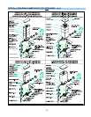
10. High Temperature Lockout Screen
Definition – This screen is displayed when the present water temperature is 10 °F above the water
temperature set point.
!SYSTEM ERROR!
TEMP SENSOR
Possible Causes: Faulty/disconnected Temperature Sensor.
11. Over Temperature / Over Flow Error Screen
Definition – This screen is displayed and the system is shut down when the present water temperature is
sensed higher than 208 °F.
!SYSTEM ERROR!
OT/OF SENSOR
Possible Causes: Faulty/disconnected Over-Temperature/Over-Flow Sensor.
12. Communications Error Screen
Definition – This screen is displayed and the system is shut down when the Communications Link
between the Display Board and the Control Board has been interrupted for more than five seconds and
then re-established.
!SYSTEM ERROR!
COMMUNICATIONS
Possible Causes: Faulty connection between the Display Board and the Control Board .
13. Communications Failure Screen
Definition – This screen is displayed and the system is shut down when the Communications Link
between the Display Board and the Control Board has been interrupted for more than five seconds.
!SYSTEM ERROR!
COM FAILURE V 1.4
Possible Causes: Faulty connection between the Display Board and the Control Board.
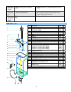
TESTS
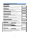
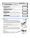
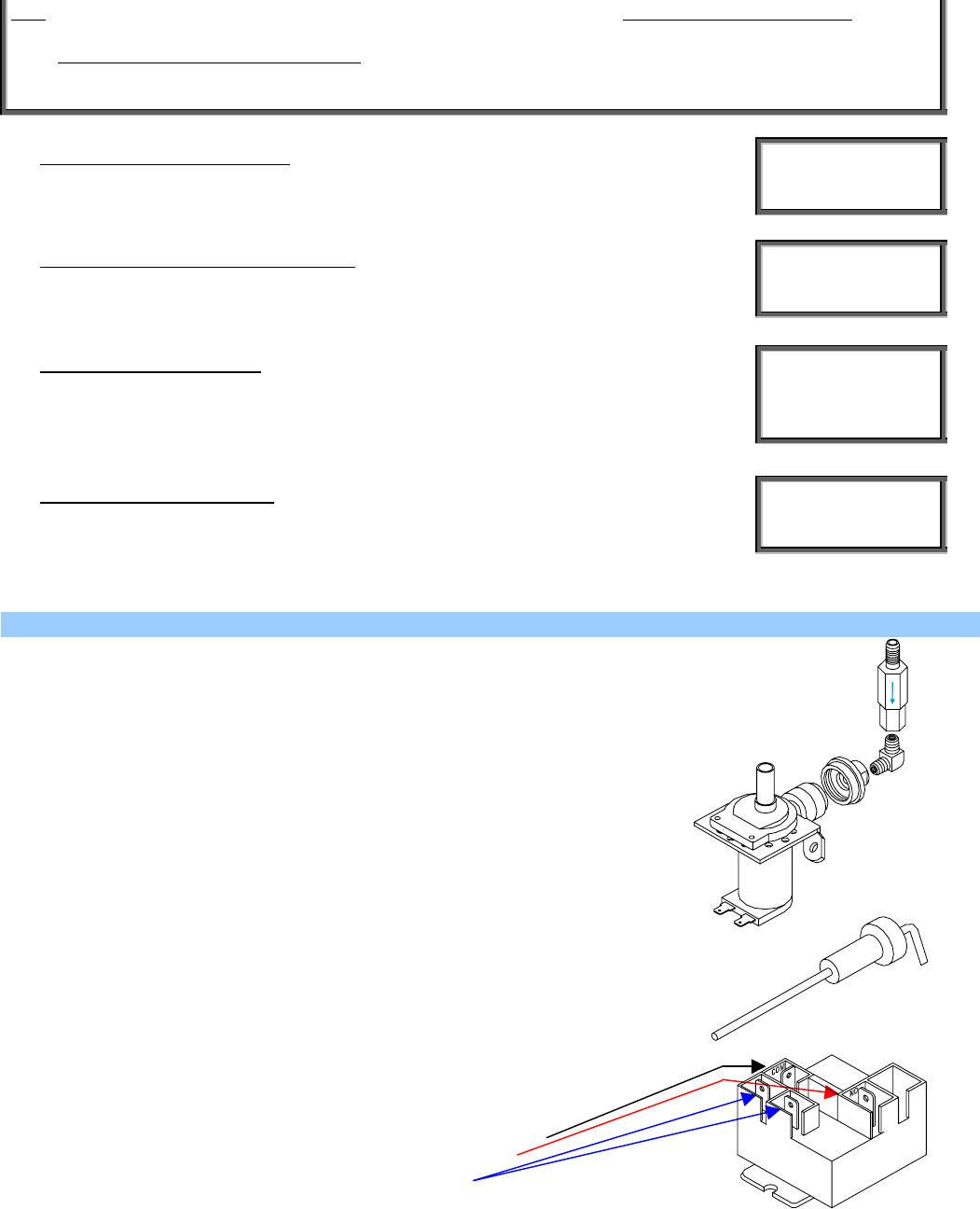
1) Water Inlet Valve Test
Turn power off. If the water level rises inside the tank, the Water Inlet Valve is leaking.
Disconnect wires from the Water Inlet Valve coil and connect a 2 wire line cord to the terminals.
Plug it into a 115V outlet. If water flows in and stops when you pull it out, the Valve is working
fine. Repeat this test a few times. The problem may be in the Probe. If the water does not flow
in when the cord is plugged into an electrical outlet, the Solenoid coil may be damaged, opened
or the valve may have an obstruction preventing the water from flowing in. Clean or replace it.
A Check Valve is installed to prevent backflow.
To check proper function of Check Valve, disconnect water line from the Check Valve, check for
dripping from the disconnected end of the Check Valve. If it leaks replace it.
2) Water Level Probe Test
If there is a lack of water, you will get an error message on the LCD window. Check the probe as
follows:
Turn on the power and water supply. Check inside the tank to make sure the water is not
touching the Probe. Pull the wire and terminal out of the Probe rod. If water starts flowing into
the tank, the Probe may be grounded, due to excessive liming. Check with Ohm meter. Clean
or replace.
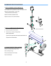
3) Relay Test
Turn Power Switch ON.
Measure Voltage across Output “COM” to Ground. Should read 120 V.
Measure Voltage across Input “NO” to Ground. Should read 120 V.
Measure Voltage across Input to Coil . Should read 24 VDC.
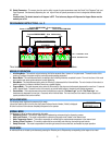
CHECK VALVE
ASS’Y L463A
HOSE NUT
ASS’Y K178A
WATER INLET
VALVE L462A