


8
Installation Instructions
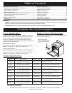
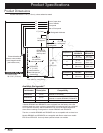
Verify the Package Contents
Verify that all the components below have been provided. If
any item is missing or damaged, please contact your dealer
immediately. Do not install a damaged or incomplete appliance.
Make sure that you have everything necessary to ensure proper
installation before proceeding.
• Use and care manual
• Anti-tip bracket with screws and anchors
• Oven racks (2) GlideRack type, (1) standard type
• Razor blade scraper
• Dacor Cooktop Cleaning Cream
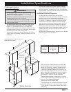
Installing the Anti-Tip Bracket
Locate the anti-tip bracket included in the parts box.
There are two ways to mount the anti-tip bracket:
• Floor mounting (preferred method).
• Wall mounting (alternate method). Use this method if floor
mounting is not suitable. If any of the conditions below exist,
then the wall mounting method can not be used and the floor
mounting method must be suitable.
The anti-tip bracket may not be mounted to the wall if:
◊ The wall contains metal stud mounting materials that
interfere with the anti-tip bracket mounting screws.
◊ The front panel of the range is further than the maximum
distance from the back wall stated on page 9.
◊ A raised vent is installed.
◊ The flooring is too thick (see Installing the Anti-Tip
Bracket on the Wall).
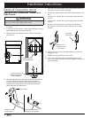
Installing the Anti-Tip Bracket on the Floor
WARNING
To perform its intended function, the anti-tip bracket must be
attached as instructed to the concrete slab or wood sub-floor
below any floor coverings (including cement board) on top. Do
not attach the anti-tip bracket directly to floor coverings such as
ceramic/asphalt tile or linoleum.
Four (4) plastic anchors are provided along with three sizes
(4 each) of #8 or #12 Phillips head screws for attaching the anti-
tip bracket to the floor. Use both the anchors and four (4) of the
#8 screws when attaching the bracket to a concrete sub-floor. Do
not use the anchors when attaching to a wood sub-floor.
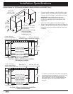
1. Determine the location of the range center line and front
panel when the range is in its final position based on the
Product Dimensions on page 4, and the actual cabinet/
cutout dimensions used for the installation.
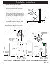
2. Determine the required position of the anti-tip bracket,
based on the diagram on the facing page. Mark the four (4)
mounting hole locations on the floor with a pencil.
3. Determine the screw size required. The minimum full thread
depth (portion of screw threaded into wood/slab) for wood
is 3/8” (1 cm) and 5/8” (1.6 cm) for concrete. See the table
below to select the correct screw size.
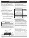
Sub-Floor Type/
Floor Covering Thickness
Screw Size
Concrete or wood sub-floor, no floor
covering over top
#8 x 1” *
Concrete or wood sub-floor, floor
covering up to 1/4” thick
#8 x 1” *
Concrete or wood sub-floor, floor
covering over 1/4” and up to 1/2” thick
#8 x 1 1/4” *
Wood sub-floor, floor covering over
1/2” and up to 1 3/16” thick
#12 x 1 3/4” *
Concrete sub-floor under floor covering
over 1/2” thick
Must be purchased
separately **
Wood sub-floor, floor covering
over 1 3/16” thick
Must be purchased
separately **
* Included with range
** Not included. Determine length based on step 3.
Attaching the bracket to a concrete floor:
• Drill four (4) 3/8” diameter countersink holes through any
existing floor covering down to the concrete slab below.
• Drill the 4 holes for the anchors 1 1/4” (3.2 cm) deep into the
concrete slab using a 3/16” masonry bit. This hole length is
longer than the anchor, but is required for proper installation.
Clear the holes of dust and any other material. Tap each
anchor into the hole until the anchor top is flush with the top
of the concrete slab. Position the anti-tip bracket holes over
the anchor holes. Insert the screws through the 4 holes in
the base of the bracket and thread them into the anchors. Be
sure the screw threads fully engage the anchor body. Tighten
the screws into place.
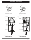
Attaching the bracket to a wood floor:
• If there is ceramic, asphalt or other hard floor covering over
the wood below, drill 4 countersink holes to allow access to
the wood below for drilling pilot holes.
• Drill 4 pilot holes into the wood floor using a drill bit (1/16”
dia. for #8 screws, 1/8” dia. for #12 screws). Position the anti-
tip bracket holes over the holes in the floor. Insert the screws
into the wood and tighten into place.
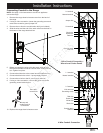
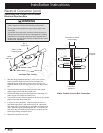
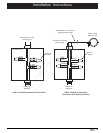
Installing the Anti-Tip Bracket on the Wall
1. To use the wall mount option, the range front panel must not
be more than 26 1/4” from the wall and the bracket screws
must be able to thread into the base plate inside the wall
behind. The notches on the sides of the bracket indicate the
minimum required height of the base plate inside the wall and
that any floor covering is not too thick for proper screw thread
engagement.
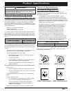
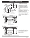
Screws attached
to sub-floor below
floor covering
Sub-floor
Concrete
anchors shown,
do not use for
wood sub-floor
Floor
covering
Anti-tip
bracket