


5
Installation Specifications
Cabinet Layout
WARNING
• Observe all governing codes and ordinances during
planning and installation. Contact your local building
department for further information.
• All minimum cabinet/countertop clearances shown on the
following pages must be met or exceeded.
• To eliminate the risk of burns or fire by reaching over heated
surface units, cabinet storage space located above surface
units should be avoided.
• The shaded areas shown below denote the location of the
electrical junction box/receptacle. This is the suggested
location. For replacement purposes, the location of the
existing electrical supply may be utilized provided that it does
not interfere with the sides or rear of the range. Verify that the
electrical service meets local building codes.
• Access to the remote circuit breaker panel/fuse box, with the
range in place and operating, must also be allowed for in the
installation.
• The electrical junction box/receptacle must be located so
that it does not interfere with the range when it is installed
and under operation. In addition, the junction box/receptacle
must be located so the range can be removed for service and
remain connected to power.
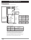
Cabinet and Countertop Preparation
• To reduce the risk of personal injury and to reduce
accumulated smoke in the room, Dacor strongly recommends
installing a range hood. A range hood should project
horizontally a minimum of five (5) inches beyond the face of
the cabinets. If installing a range hood, see the range hood
specifications for minimum clearances. If cabinet storage
space is to be provided directly above the range, the risk of
personal injury may be reduced by installing a range hood.
• The range may be installed flush to the rear wall. Dacor
recommends installing a non-combustible material on the rear
wall above the range and up to the range hood or cabinet,
whichever is lower.
• Any openings in the wall behind the appliance and in the floor
under the appliance must be sealed.
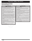
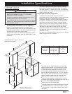
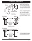
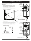
Note 2
B
A
Non-combustible
surface along
back wall
recommended
Top of
finished
counter
13” (33.0 cm)
max.
4
18” (45.7 cm)
min.
4
C
Suggested
location of
utilities
3
Note 5
Note 1
Cutout tolerances: +1/16” (+1.6 mm), -0,
unless otherwise stated.
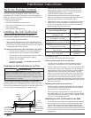
Cabinet Dimensions
1
30” (76.2 cm) min. vertical clearance from top of the
cooking surface to bottom of uncovered wood or metal
cabinet. 24” (61 cm) min. clearance if bottom of wood
or metal cabinets are protected by not less than 1/4“
(0.6 cm) flame retardant millboard covered with no less
than No. 28 MSG sheet steel 0.015” (0.04 cm) stainless
steel, or 0.024” (0.06 cm) aluminum or 0.020” (0.05 cm)
copper. If installing range hood, also check the hood
specifications for minimum required clearances.
2
Cabinet/countertop depth is at discretion of customer
but cabinet face SHALL NOT protrude further than rear of
front panel. See Product Dimensions.
3
Consult local code for requirements.
4
This specification not applicable for cabinets more than
a horizontal distance of 1” (2.6 cm) from edge of range.
5
1” (2.6 cm) min. to combustible sidewalls above range
(both sides).
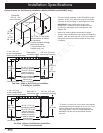
A* B C*
30 1/16” min.
(76.3 cm)
36” (91.4 cm)
recommended
30” (76.2 cm)
min.
37”
(94.0 cm)
max.
*For self rimming installations, see required dimensions
for “A” and “C” on the following pages.