


6-12
The temperature probe is used only when the unit is in the simmer mode. When the operator
selects the simmer mode, logic circuits in the computer monitor the temperature of the water and
cycle power to the element on and off as required to maintain the temperature at the setpoint
programmed into the computer.
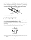
The contactor is the terminal block to which the element leads are connected and where actual
contact is made between the leads and the line voltage. Built into the contactor is a 24VAC coil that
energizes when the master ON/OFF switch is placed in the ON position. When it energizes, contact
is made between the incoming line voltage and the element leads, and line voltage is supplied to one
side of the element circuit. The solid-state relays control the supply of line voltage to the other side
of the element circuit. The relays are closed when the computer is calling for heat and open when it
is not.
The element is a resistive heating device. That is, when voltage is applied to the element, the
element gets very hot due to its resistance to current flow through it. The heat generated is
transferred directly to the water in which the element is immersed.
The computer is the interface between the operator and the other components of the equipment. In
the water heating system, its function is to control the application of line voltage to the heating
element via the solid-state relays.
When in the Simmer Mode, the signal from the computer is continuous, the solid-state relays are
continuously closed, and line voltage is applied to the elements until the simmer setpoint
(195ºF/90.6ºC) is reached.
When in the Boil Mode, the signal from the computer is continuous for approximately the first 40
seconds, then changes to a series of on-off pulses of equal duration. The solid-state relays close
and open in response to the signal from the computer, and line voltage is applied to the elements
accordingly. (The pulsing of the line voltage to the elements prevents the water in the cookpot
from reaching a vigorous, roiling boil. This, in turn, minimizes the formation of starch foam. An
added benefit of the pulsing is reduced electrical power consumption.)
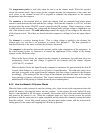
6.4.5 How the Basket Lift System Works
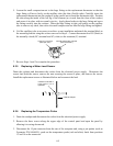
When the Start switch is pressed to start the cooking cycle, logic circuits in the computer activate the
basket lift motors, lowering the basket into the cookpot. As the motors drive the basket lift arms
down, a cam attached to the left motor eventually loses contact with a roller-activated microswitch
and power to the motors is cut. When the computer times out, logic circuits reverse the switch
positions so that the motor circuit is again completed and the motors are restarted, raising the basket
from the cookpot. At the fully raised position, the cam again makes contact with the microswitch,
cutting power to the motors and stopping the lift in the up position.