


7-7
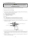
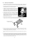
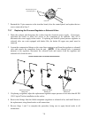
6. Carefully work any slack in the capillary tube back out of the hole in the cookpot. Apply thread
sealer to the threads of the replacement temperature probe fitting and screw the fitting into the
cookpot. When the fitting is tight, verify that all slack in the capillary has been worked back
out of the cookpot and that the bulb is correctly positioned under the lower portion of the
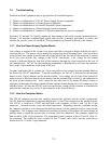
retaining bracket. Then, and only then, tighten the small nut in the center of the fitting. NOTE:
Tightening the small nut crimps the internal compression fitting onto the capillary and
prevents any further movement of the capillary through the large fitting.
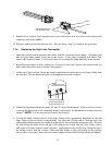
Tighten the large fitting
before tightening the
small compression nut.
Tighten the small
compression nut last.
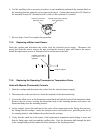
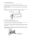
7. Position the thermostat body in the mounting bracket with the terminals to the left and reinstall
the two screws removed in Step 3. Reinstall the thermostat knob.
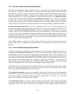
8. Reconnect rocker-switch wires 20C and 35C to the lower terminal of the thermostat body;
reconnect wire 15C to the top terminal. Reinstall the probe cover to complete the procedure.
Attach wires 20C and 35C here.
Attach wire15C here.
Units with Computer Controls
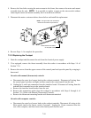
1. Drain the cookpot and disconnect the cooker from the electrical power supply.
2. Remove the screws from the upper corners of the control panel and open the panel by allowing it
to swing downward.
3. Disconnect the 12-pin connector from the interface board and, using a pin pusher, push out the
temperature probe leads from holes 6 and 8 on the connector.
4. Remove the temperature probe by unscrewing it from the front of the cookpot.
5. Apply thread sealer to the replacement probe and screw it securely into the cookpot.
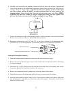
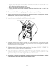
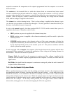
6. Insert the probe leads into holes 6 and 8 of the 12-pin connector (there is no polarity; either lead
may be inserted into either hole [see illustration at top of next page]). Pull gently on each lead to
ensure it is firmly seated.