7-17
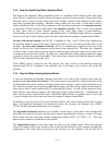
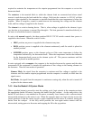
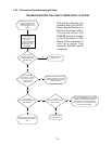
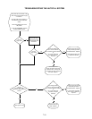
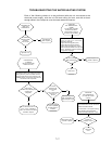
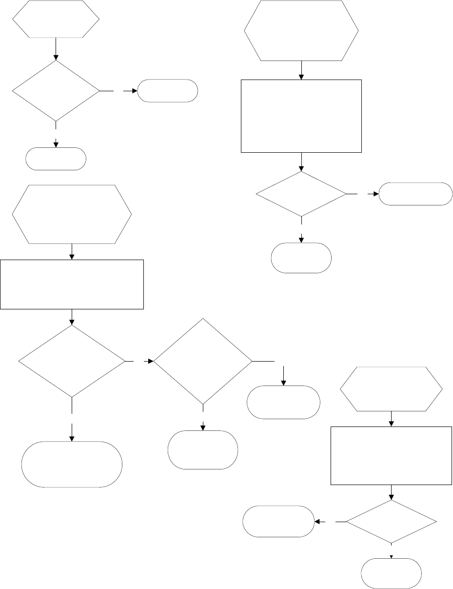
TROUBLESHOOTING THE WATER HEATING SYSTEM
Each of the following checks is to be performed with the unit connected to the
electrical power supply, with the unit ON and calling for heat, and with at least
enough water in the cookpot to cover the lower water-level sensor.
Is resistance
between outside
terminals
1 ohm or less?
High-limit has
failed. Replace.
High-limit is OK.
Yes
No
CHECKING THE
HIGH-LIMIT
THERMOSTAT
CHECKING THE
ELEMENT
(24VAC Power Supply
verified to be OK..)
Was there an
audible snap indicating the
contactor coil
energized?
No
Yes
With sufficient water in the cookpot to cover the
heating element, place the POWER switch in
the ON position and the CYCLE switch in the
SIMMER position, OR press the computer ON/
OFF switch to the ON position.
Ohm out elements (Pins 1 & 6,
2 & 5, 3 & 4). If resistance
is NOT 15 ±3 Ohms, the element
has failed. Replace.
Is 24VAC
present on the
CYCLE switch
OR
on Pin 4 of the 15-pin
connector on
the IFB.
Probable causes,
in order of probabilty,
are failed switch or
contactor.
Probable causes, in
order of probabilty, are
failed computer or IFB.
Yes
No
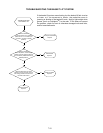
CHECKING
THE TEMPERATURE
PROBE
(on units with computers
because water boils in
Simmer Mode or water is
too cool in Simmer Mode.)
Check probe resistance between Pins 6
and 8 on IFB 12-pin connector.
Resistance should be:
Approx 552 ohms @ 60ºF (16ºC)
Approx 655 ohms @ 100ºF (38ºC)
Approx 1000 ohms @ 212ºF (100ºC)
Check resistance between each pin and
ground. Resistance on BOTH should be
2 mega-Ohms or greater.
Are BOTH readings
within specification?
Probe is open or is
shorted. Replace.
Probe is OK.
No
Yes
CHECKING
THE THERMOSTAT
(on units with manual
controls.)
Set thermostat knob to OFF position.
Check resistance across terminals.
Resistance should be infinite.
Set thermostat to its highest setting.
Check resistance across terminals.
Resistance should be less than 1 ohm.
Are BOTH
readings correct?
Thermostat is open or
is shorted. Replace.
Thermostat
is OK.
No
Yes


