


7-14
required to maintain the temperature at the setpoint programmed into the computer or set on the
thermostat knob.
The contactor is the terminal block to which the element leads are connected and where actual
contact is made between the leads and the line voltage. Built into the contactor is a 24VAC coil that
energizes when signaled by the computer or interface board that the water temperature is below the
setpoint. When it energizes, contact is made between the incoming line voltage and the element
leads, and line voltage is supplied to the element.
The element is a resistive heating device. That is, when voltage is applied to the element, it gets
very hot due to its resistance to current flow through it. The heat generated is transferred directly to
the water in which the element is immersed.
In units with manual controls, the three-position HEAT CYCLE switch controls how power is
supplied to the element. When the switch is in the:
• IDLE position, no power is supplied to the element at any time.
• BOIL position, power is supplied to the element continuously until the switch is placed in
another position.
• SIMMER position, power to the element cycles on if the water temperature is below the
temperature indicated by the thermostat knob. When the temperature reaches that indicated
by the thermostat knob, power to the element cycles off. This process continues until the
switch is placed in another position.
In units equipped with a computer, the computer is the interface between the operator and the other
components of the equipment. It controls the application of line voltage to the heating element via
the contactor. There are two modes of operation:
Simmer Mode, the signal from the computer is continuos and line voltage is applied to the
elements until the simmer setpoint programmed into the computer is reached, at which time the
signal ceases.
Boil Mode, the signal from the computer is continuous ceasing only when the unit is turned off
or placed in the simmer mode.
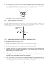
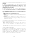
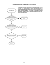
7.4.5 How the Basket Lift System Works
When a product button is pressed to start the cooking cycle, logic circuits in the computer activate
the appropriate basket lift motor, lowering the basket into the cookpot. As the motor drives the
basket lift rod down, a cam attached to the motor eventually loses contact with a roller-activated
microswitch and power to the motor is cut. When the computer times out, logic circuits reverse the
switch positions so that the motor circuit is again completed and the motor is restarted, raising the
basket from the cookpot. At the fully raised position, the cam again makes contact with the
microswitch, cutting power to the motor and stopping the lift in the up position.