


2-4
c. Place the fryer power switch in the OFF position. Verify that the power and heat lights are
out, or that the display shows “OFF”.
5. Refer to the data plate on the inside of the fryer door to determine if the fryer burner is config-
ured for the proper type of gas before connecting the fryer quick-disconnect device or piping
from the gas supply line.
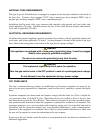
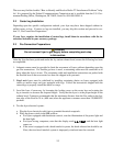
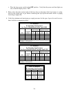
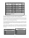
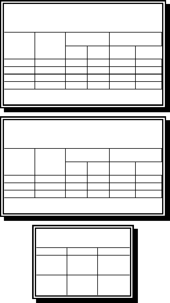
6. Verify the minimum and maximum gas supply pressures for the type of gas to be used in accor-
dance with the accompanying tables.
Orifice Diameter
Single
Vat
Dual
Vat
Single
Vat
Dual
Vat
G20 20 2 x 3.40 2 x 3.40 7 mbar 6.5 mbar
G25 20 or 25 2 x 3.40 2 x 3.40 10 mbar 9 mbar
G30 28/30 or 50 2 x 2.05 2 x 2.05 17 mbar 17 mbar
G31 37 or 50 2 x 2.05 2 x 2.05 20 mbar 18.5 mbar
CE Standard
for Incoming Gas Pressures
for Fryers Manufactured After April 1999
(1) mbar = 10.2 mm H2O
Gas
Pressure
(mbar)
(1)
Regulator Pressure
Orifice Diameter
Single
Vat
Dual
Vat
Single
Vat
Dual
Vat
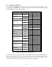
G20 20 2 x 3.40 2 x 3.40 7 mbar 6.5 mbar
G25 20 - 25 2 x 3.40 2 x 3.40 10 mbar 9 mbar
G31 37 - 50 2 x 2.05 2 x 2.05 20.2 mbar 18.5 mbar
CE Standard
for Incoming Gas Pressures
for Fryers Manufactured Through April 1999
(1) mbar = 10.2 mm H2O
Gas
Pressure
(mbar)
(1)
Regulator Pressure
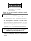
Non-CE Standard
for Incoming Gas Pressures
Gas Minimum Maximum
Natural
6" W.C.
1.49 kPa
14.93 mbar
14" W.C.
3.48 kPa
34.84 mbar
LP
11" W.C.
2.74 kPa
27.37 mbar
14" W.C.
3.48 kPa
34.84 mbar